TM-5-2350-378-24-P - Page 356 of 790
TM 5--2350--378--24&P
0016 00--53
HYDRAULIC OIL OVERHEATS -- Continued
0016 00
EJECTOR RELIEF VALVE ADJUSTMENT -- CONTINUED
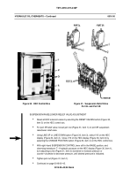
Disable ejector; manually close V23 (Figure 38, item 1) on the DCV bank.
Using LINE UP or LINE DOWN button (Figure 39, item 3), select V1 on the HDC display
(Figure 39, item 2). Close V1 on the HDC display (Figure 39, item 2) by selecting the
CHANGE POSITION button (Figure 39, item 4) on the HDC control box.
Start engine.
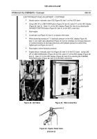
Loosen jam nut (Figure 40, item 1) on ejector relief valve.
While observing transducer T--2 hydraulic pressure on the HDC display (Figure 39,
item 1); turn relief valve adjustment (Figure 40, item 2) clockwise (to increase pressure)
or counterclockwise (to decrease pressure) until hydraulic pressure is within limits.
Tighten jam nut (Figure 40, item 1).
Stop engine; relieve hydraulic pressure.
Enable ejector; manually open V23 (Figure 38, item 1) on the DCV bank. Using LINE
UP or LINE DOWN button (Figure 39, item 3), select V1 on the HDC display (Figure 39,
item 2). Open V1 on the HDC display (Figure 39, item 2) by selecting the CHANGE
POSITION button (Figure 39, item 4) on the HDC control box.
Figure 38. DCV Bank
Figure 39. HDC Control Box
Figure 40. Ejector Relief Valve
Back to Top


