TM-5-2350-378-24-P - Page 482 of 790
TM 5--2350--378--24&P
0021 00--19
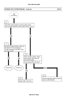
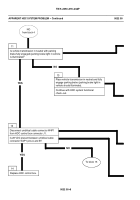
WINCH WILL NOT PULL RATED LOAD -- Continued
0021 00
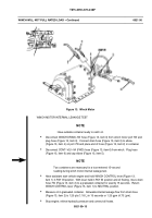
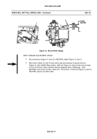
Figure 15. Winch Linkage
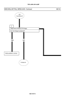
WINCH HIGH/LOW LINKAGE ADJUSTMENT
NOTE
S
Ensure control lever is in NEUTRAL detent.
S
Control lever must move 0.10 in. (2.54 mm) in either direction without
engaging winch. Total NEUTRAL travel zone is 0.34 in. (8.64 mm).
Remove cotter pin (Figure 15, item 4) and clevis pin (Figure 15, item 1) from clevis
(Figure 15, item 2) and control lever (Figure 15, item 5). Discard cotter pin (Figure 15,
item 4).
Pull shift rod (Figure 15, item 3) out as far as possible. This is the end of travel in the
high--gear position.
Push shift rod (Figure 15, item 3) back in 1.220 in. (30.99 mm) to locate center of
NEUTRAL position.
Adjustment can be made by turning clevis (Figure 15, item 2) clockwise for NEUTRAL
position out; counterclockwise for NEUTRAL position in.
Install clevis (Figure 15, item 2) on control lever (Figure 15, item 5) with clevis pin
(Figure 15, item 1) and new cotter pin (Figure 15, item 4). Verify shift rod (Figure 15,
item 3) is within NEUTRAL travel limits.
Operate winch and check for proper operation. If winch does not function properly,
notify Direct Support maintenance.
Back to Top

