TM-5-2350-378-24-P - Page 478 of 790
TM 5--2350--378--24&P
0021 00--15
WINCH WILL NOT PULL RATED LOAD -- Continued
0021 00
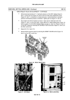
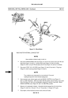
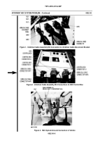
Figure 13. Winch Motor
WINCH MOTOR INTERNAL LEAKAGE TEST
NOTE
Have suitable container ready to catch oil.
Disconnect WINCH DRAIN--7W hose (Figure 13, item 3) from winch motor port 7W and
plug hose (Figure 13, item 3). Connect drain hose (Figure 13, item 2) to elbow
(Figure 13, item 4) on port 7W and place end of hose (Figure 13, item 2) in container.
Disconnect CONT--VLV--VA (FWD) hose (Figure 13, item 6) from winch. Plug hose
(Figure 13, item 6) and cap elbow (Figure 13, item 5).
NOTE
Two containers are necessary for a true metered 15--second
reading during winch motor internal leakage test.
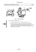
Have assistant start vehicle engine and hold WINCH CONTROL lever (Figure 13,
item 1) in PAY IN position. With lever held in PAY IN position and oil flowing, move drain
hose 7W (Figure 13, item 2) to a graduated container for exactly 15 seconds. Return
WINCH CONTROL lever (Figure 13, item 1) to NEUTRAL position.
Measure oil in graduated container. Allowable internal leakage flow from drain hose
(Figure 13, item 2) is 1.25 qts (1.18 L) in 15 seconds or 1.25 gpm (4.73 Lpm).
Stop engine; relieve hydraulic pressure and connect all hoses.
Back to Top


