TM-5-2350-378-24-P - Page 519 of 790
TM 5--2350--378--24&P
0022 00--36
APPARENT HDC SYSTEM PROBLEM -- Continued
0022 00
YES
YES
from block 64
66
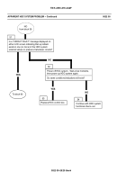
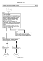
Disconnect the W2 or W3 cable assembly electrical
lead going to the electrical connector of the solenoid
valve on the primary manifold, forward manifolds, or aft
manifold identified in the “CIRCUIT FAULT” message.
Reference the individual cable assembly wiring
schematic diagrams (for cable assemblies W2 through
W4) in FP--23 through FP--28, and the HDC control box
connectors pin number signal names information in WP
0005 00, and trace the signal path for the “CIRCUIT
FAULT” solenoid valve energizing voltage (28 VDC) from
a connector on the HDC control box (J2 or J3) to a
connector on the umbilical disconnect bracket (W2J1 or
W3J1), through umbilical cable connectors W4P5 or
W4P6, respectively.
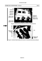
Disconnect umbilical cable connector W4P5 or W4P6
(as applicable) associated with “CIRCUIT FAULT”
solenoid valve from cable assembly W2J1 or cable
assembly W3J1 (as applicable) connector on umbilical
disconnect bracket.
Perform continuity test and check for short circuit to
cable ground (connector case/shell) for the two
pins/wires in the applicable embedded cable assembly
(W2J1 or W3J1) that route the 28 VDC energizing
voltage from the HDC control box to the solenoid valve
associated with the “CIRCUIT FAULT” message (28
VDC energizing voltage is applied between pins 1 and 2
on the three--pin solenoid valve electrical connector on
all solenoid valves).
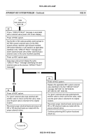
Does an open circuit or short circuit exist in the
applicable cable assembly W2 or W3 wiring circuit
(”CIRCUIT FAULT” solenoid valve 28 VDC energizing
circuit) being checked? (Refer to FP--23 through FP--26)
for wiring schematic diagrams of electrical cable
assemblies W2 and W3).
To block 68
NO
NO
67
Replace embedded cable assembly (W2 or W3
(WP 0029 00 or WP 0030 00), as applicable))
associated with designated “CIRCUIT FAULT”
solenoid valve 28 VDC energizing circuit wiring.
Back to Top


