TM-5-2815-241-34-P - Page 392 of 738
TM 5-2815-241-34&P
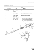
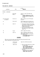
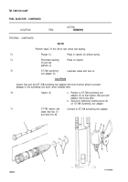
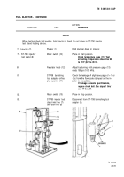
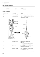
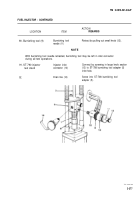
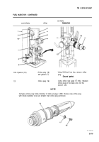
FUEL INJECTOR - CONTINUED
ACTION
LOCATION
ITEM
REMARKS
TESTING - CONTINUED
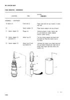
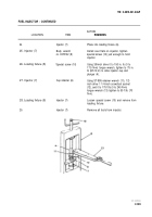
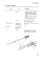
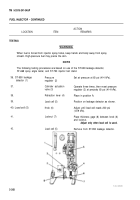
47.
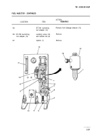
Injector (1)
48.
Knob (3)
49.
Transfer line (6)
50.
T-handle clamp (8)
51.
Retraction lever (9)
52.
Plunger (10)
53.
54.
55.
56.
57.
Retraction lever (9)
Shift from position B to position A.
T-handle clamp (8)
Loosen.
Bubble checker (12)
Observe.
Transfer line (6)
Pressure
regulator (13)
Install on support plate (2) and clamp into
position.
Support plate may be tilted for easier
Installation.
Adjust to obtain proper clearance with
thickness gage (4) between knob and
locknut (5).
Screw in and tighten in injector drain
port (7).
Tighten.
Shift from position A to position B, making
sure plunger (10) retracts.
Rotate in clockwise direction by small lncre-
ments, observing airflow meter (11). Stop
rotation when highest reading is obtained.
If airflow meter indicates in excess of
4.5, replace injector barrel and
plunger.
This applies 200 lb (90.8 kg) load to
plunger.
If bubbles occur In 10 seconds, or If
time Interval between consecutive
bubbles exceeds 5 seconds, replace
injector cup.
Unscrew and remove from injector drain
port.
Release air pressure.
2-370
Back to Top


