TM-5-3805-254-14-P-2 - Page 252 of 894
MOTOR TRUCK SERVICE MANUAL
COOLING SYSTEM
GENERAL
Remove left angle (1) and right angle (3) from
shutter blades (10).
CLEANING, INSPECTION AND REPAIR
Clean all parts thoroughly and examine for damage
or wear.
Be sure all old gasket material is removed from
body.
Check to see that small disc (antifriction washer),
located in bore of thermostat unit, is not stuck to lower
end of piston.
If disc is stuck it is very important that it
boe replaced.
Be certain that piston is free of dirt or
abrasive material.
Also, see that piston is a free sliding
fit in bore of thermostat unit.
Check linkage and shutter blade crank bushings for
excessive wear.
Replace parts where necessary.
REASSEMBLY
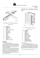
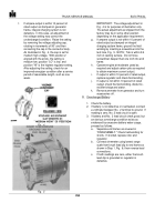
Shutter Control
All key numbers refer to Fig.
2.
Using proper adapter, drive or press new bushings in
body flanges.
Install small disc (antirattle washer) into bore of
thermostat unit.
Lubricate piston with # 200 fluid or
silicone grease and place piston into bore of thermostat
unit (bulletnose end out).
Assemble jam nut (6) followed
by new "O" ring seal (5) on thermostat unit (7).
Install
thermostat into body (3).
See "ADJUSTMENTS" for
correct positioning of thermostat in body.
Position seat (9) in body (3), flanged side opposite
thermostat side of body.
Install spring (10), seat (11), felt
washer (12) and secure in body (3) with snap ring (13).
Place plunger (14) into body.
Slide control shaft (8)
through one side of body flange.
Mount yoke with plunger assembly (14) on shaft.
Push
shaft through remaining flange.
Align plunger with opening in seats (11) and position
yoke on shaft so that there is no interference when
plunger moves in and out of body.
Install and tighten
socket head setscrews in yoke.
Position control lever (1)
on shaft with lever pointing in opposite direction from
thermostat unit.
Do not tighten clamp bolt or setscrews
in lever at this time.
See "ADJUSTMENTS" for final
positioning of lever.
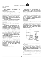
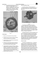
Shutter Assembly
All key numbers refer to Fig.
3.
Install bushings (11) on shutter blades (10).
Assemble left angle (1) and right angle (3) on ends of
blades (10).
Place bushings (12) on blade crank pins
and install control bar (4).
Place shutter blade assembly in frame (2).
Connect
blade spring (5) from control bar (4) to control bar stud
(6).
Insert control rod (9) and install block (8) and spring
(7) on rod.
Install cotter pins in control rod.
Connect
block (8) to control bar (4).
Install bolts securing right
angle (3) and left angle (1) to frame (2).
INSTALLATION
Shutter Assembly
Position shutter assembly in vehicle and install retaining
bolts.
Shutter Control
Adjust thermostat location in control body (see
"ADJUSTMENTS").
Place new gasket on control body
and assembly body to radiator, thermostat unit extending
into bottom tank.
Install the two (2) bolts securing
shutter control to radiator tank.
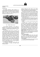
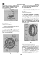
Fig. 4
Shutter Control Thermostat Unit Adjustment
.
ADJUSTMENTS
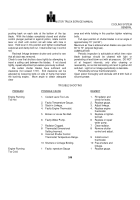
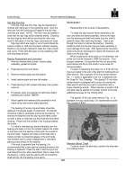
Thermostats with different body lengths are being
used, see Figures 4 and 5.
Therefore, the dimensions
between the face of the body flange and end of the
thermostat unit will also be different as shown in the
illustrations.
When installing shutter control, control lever must be
correctly positioned on shaft to properly open and close
shutter blades.
With engine cold (150° or below) and control rod
disconnected at control lever, manually close shutter
blades.
This can be done by
248
Back to Top

