TM-5-3805-254-14-P-2 - Page 257 of 894
ELECTRICAL
TRUCK SERVICE MANUAL
1.
Do not polarize the integral charging system.
2.
Do not short across or ground any of the terminals in
the charging circuit except as specifically instructed
herein.
3.
Make sure the integral charging system and battery
have the same ground polarity.
4.
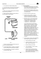
When connecting a charger or a booster battery to
the vehicle battery, connect negative
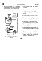
Fig.
3
Trouble in the charging system will show up as one
or more of the following conditions:
A. An undercharged battery or energizer, as evidenced
by slow cranking and low specific gravity readings.
B. An overcharged battery or energizer, as evidenced
by excessive water usage.
A. Undercharged Battery
This condition, as evidenced by slow cranking
and low specific gravity readings, can be caused
by one or more of the following conditions:
1.
Insure that the undercharged condition has not
been caused by accessories having been left on
for extended periods.
2.
Check the drive belt for proper tension.
3.
Inspect the wiring for defects.
Check all
connections for tightness and cleanliness,
including the cable clamps and battery posts.
4.
With ignition switch on and all wiring harness
leads connected, connect a volt-meter from:
a.
generator "BAT" terminal to ground.
b.
generator No.
1 terminal to ground.
c.
generator No.
2 terminal to ground.
A zero reading indicates an open between
voltmeter connection and battery or energizer.
NOTE :An open No.
2 lead circuit on early
production generators caused uncontrolled
voltage, battery overcharge and possible
damage to battery and accessories.
Generators
supplied for later applications have a built-in
feature which avoids overcharge and accessory
damage by preventing the generator from
turning on if there is an open in the wiring
harness connected to the No.
2 generator
terminal.
Opens in the wiring harness connected
between the No.
2 generator terminal and
battery may be between the terminals, at the
crimp between the harness wire and terminal, or
in the wire.
5.
If previous steps 1 through 4 check satisfactorily,
check integral charging system as follows:
a.
Disconnect battery ground cable.
b.
Connect an ammeter in the circuit at the
"BAT"’ terminal of the alternator.
c.
Reconnect battery ground cable.
d.
Turn on accessories.
Connect a carbon
pile across the battery.
e.
Operate engine at moderate speed as
required, usually 4000 generator RPM or
more, and adjust carbon pile as required to
obtain maximum current output.
253
Back to Top

