TM-5-3805-254-14-P-2 - Page 500 of 894
TRUCK SERVICE MANUAL
FUEL SYSTEM
PT Fuel Pump Group
OPERATING PRINCIPLES
The operation os the Cummins PT Fuel System is based
on the principle that the volume of liquid flow is
proportionate to the fluid pressure, the time allowed to
flow and the size of passage the liquid flows through.
To
apply this simple principle to the Cummins PT Fuel
System, it is necessary to provide:
1.
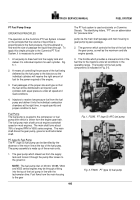
A fuel pump to draw fuel from the supply tank and
deliver it to individual injectors for each cylinder.
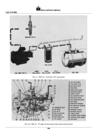
Fig.
5-1.
2.
A means of controlling the pressure of the fuel being
delivered by the fuel pump to the injectors so the
individual cylinders will receive the right amount of
fuel for the power required of the engine.
3.
Fuel passages of the proper size and type so that
the fuel will be distributed to all injectors and
cylinders with equal pressure under all speed and
load conditions.
4.
Injectors to receive low-pressure fuel from the fuel
pump and deliver it into the individual combustion
chambers at the right time, in equal quantity and
proper condition to burn.
Fuel Pump
The fuel pump is coupled to the compressor or fuel
pump drive which is driven from the engine gear train.
The fuel pump main shaft turns at engine crankshaft
speed on most engines.
The main shaft turns about
78% of engine RPM in V555 series engines.
The main
shaft drives the gear pump, governor and tachometer
shaft.
PT (type G) Fuel Pump
The PT (type G) fuel pump can be identified by the
absence of the return line at the top of the fuel pump.
The pump assembly is made up of three main units.
1.
The gear pump which draws fuel from the supply
tank and forces it through the pump filter screen to
the governor.
NOTE
: The fuel pump inlet on V6140, V8185, V504
and V555 series engines may be through a fitting
into the top of the fuel pump in line with the
tachometer drive. Fuel flows from the main housing
to the gear
The PT fuel system is used exclusively on Cummins
Diesels.
The identifying letters, "PT" are an abbreviation
for "pressure-time."
pump via the main shaft passage and main housing to
gear pump by-pass passage.
2.
The governor which controls the flow of the fuel from
the gear pump, as well as the maximum and idle
engine speeds.
3.
The throttle which provides a manual control of the
fuel flow to the injectors under all conditions in the
operating range.
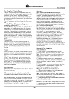
The location of the fuel pump
components is indicated in Fig. 5-3.
Back to Top


