TM-5-3805-254-14-P-2 - Page 503 of 894
TRUCK SERVICE MANUAL
FUEL SYSTEM
Front Drive Cover And Governor Plunger
1.
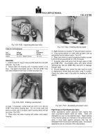
To remove drive cover from main housing, tap edge of
cover lightly with a plastic hammer to loosen.
Lift cover off
dowels and discard gasket.
Note
: Never use a steel hammer on aluminum, or on a
finished surface, it can cause extensive damage.
3.
Remove weight assist plunger, spring and shims from
weight carrier assembly.
Slide governor plunger from
barrel.
Caution: Place plunger where it will not be damaged, a
slight nick can cause extensive damage.
Throttle Assembly - Drive Screw Cover Plate Type
1.
Remove snap ring from inside housing.
Remove drive
screws securing cover plate.
Pull throttle assembly from
housing.
Remove "O" ring and discard.
Filter Screen
1.
Screw off screen cover on top of main housing.
Lift
cap, spring and filter screen assembly from main housing;
discard "O" ring.
Tachometer Drive
1.
Remove tachometer drive cover screws.
2.
Lift drive cover from main housing or front cover.
Discard gaskets, when used.
3.
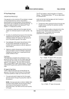
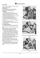
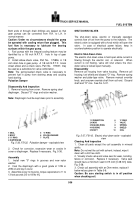
Carefully drive tachometer drive assembly from pump,
using a brass punch and hammer or use ST-667-10 collet
with ST-667 Dowel Puller or use ST-1326 to pull
tachometer seal, shaft and bushing.
Fig.
5-15.
4.
Remove oil seal and dust seal, when used, from shaft
and discard.
Throttle Assembly-Retaining Ring
Type
Compress throttle plate retaining ring and remove from
groove.
Pull throttle assembly from pump.
The throttle
shaft is a select fit in its sleeve and sizes are identified by
color code.
Note
: Handle throttle shaft with care.
Back to Top


