TM-5-3805-254-14-P-2 - Page 491 of 894
TRUCK SERVICE MANUAL
FUEL SYSTEM
Check 8 - Air Pressure Regulator
Cause
Excessive moisture.
Regulated pressure "creeps."
Check 9 - Hydraulic Clamping
Cause
Leaks-(hydraulic clamping system).
This may be verified by the following check:
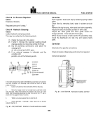
(1) Clamp the load-cell in the stand.
(2) If after 3 minutes the load-cell reading should
change position by more than 20 lbs [9.07 kg].
(3) Dry all plumbing connections and watch for
seepage with
air valve closed and with it open.
(4) If no external seepage is indicated and the
condition still
persists, one of the following exists.
If 1/32 inch clearance has been affected because of loose set screw or
any other condition, the following steps should be taken to obtain
proper clearance.
1.
Loosen set screw so that shaft slides freely in housing.
2.
Manually engage clutch by fully depressing solenoid (inside
main housing).
With clutch held in this position, the cross pin in the
clutch shaft should be positioned to clear the end of the "U" slot in
clutch driver by approximately 1/32 inch.
3.
Tighten set screw against flat on clutch shaft.
4.
Check operation, if solenoid is noisy (loud hum or chatter)
recheck Step No. 2.
Fig. 6-1-122, F601060.
Position of collar and drive clutch
Correction
Drain regulator bowl each day by releasing spring loaded
valve.
Clean filter by removing bowl, wash in solvent and air
dry.
Remove the top housing, valve seat and valve assembly.
Inspect the disc and seating surface of valve seat.
Inspect the valve guide and valve guide recess for
foreign particles.
Clean all parts thoroughly.
While the top housing is removed for the preceding step,
check the diaphragm and slip ring and replace faulty
parts.
Correction
(See below for specific corrections.)
Check for leaks at bleed plug and correct as required.
Correct as required.
Fig. 6-1-123, F60159.
Hydraulic loading cylinder
486
Back to Top


