TM-5-3805-254-14-P-2 - Page 600 of 894
TRUCK SERVICE MANUAL
PROPELLER SHAFT
General
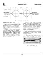
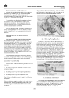
Fig. 4.
Universal Joint Speed Fluctuations
UNIVERSAL JOINT CANCELLATION
A single universal joint operating between two shafts
at a given angle will not turn at an even and constant
speed; that is to say that, although the speed of the
driving shaft is constant, the driven shaft speed is going
to fluctuate up and down.
During the first 90 degrees of rotation, the forward
universal joint speed will increase, Fig. 4.
From 90
degrees to 180 degrees the speed will decrease to again
match the driving shaft speed.
This sequence is again
repeated respectively from 180 degrees to 270 degrees
and from 270 degrees to 360 degrees.
This speed
fluctuation is known as torsional excitation (winding up
and unwinding) of the propeller shaft.
If two joints are placed in the drive line, one at each
end of the propeller shaft, having equal working angles,
the rear joint will provide the inverse condition of the
forward joint.
In other words, the rear joint will slow down
by the same amount that the forward joint speeds up,
resulting in joint cancellation.
The driving and driven
shafts will turn at constant and identical speeds.
PROPELLER SHAFT PHASING
Propeller shaft phasing is the relative positioning of
one yoke or flange with another on the same shaft within
a 360 degree revolution.
Correct phasing is equally important when compared
with other factors governing proper drive line operation.
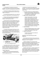
Fig. 5.
Propeller Shaft in Phase
593
Back to Top


