TM-5-3805-254-14-P-2 - Page 607 of 894
TRUCK SERVICE MANUAL
PROPELLER SHAFT
General
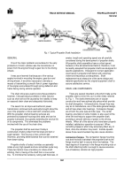
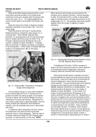
Fig.
16
Rear Axle Pinion Shaft and Engine Crankshaft Horizontal Center Lines Parallel
It should be remembered that even with the "broken
back" drive line, the working angles of both universal
joints are equal; however, the flanges will not be parallel.
This condition is permissible and should provide
satisfactory drive line operation.
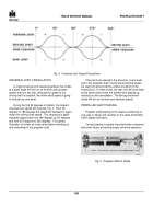
To determine the correct vertical angle of a "broken
back" type drive line flange, extend the center line of the
driving (output) and driven shafts.
These lines should
intersect at a point exactly midway between the joint
centers, Fig.
3.
Correction of a vertically misaligned rear axle pinion
shaft flange can be accomplished by placing tapered
shims or wedges between the spring pads and the
springs to tilt the pinion shaft up or down.
The angle of
the shims or wedges will depend upon the amount of
existing vertical misalignment.
Recheck flange alignment after shims or wedges
have been installed.
NOTE:
Be sure when installing wedges or shims
that the same thickness is used at each spring pad
to prevent inducing a strain on the axle housing or
springs.
Main Transmission Companion Flange Horizontal
Alignment
The horizontal alignment of all flanges is just as
important as the vertical alignment.
Place the vehicle on a level floor.
Clamp a straight edge on the main transmission
companion flange so it will project equally from each side
of the flange.
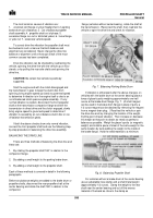
Place an SE-2067 magnetic base
protractor on the straight edge to be sure that it is exactly
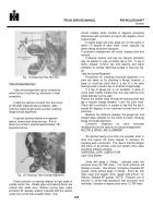
horizontal, Fig.
17.
Fig.
17 Checking Horizontal Alignment of Propeller Shaft
Obtain a second straight edge at least 12" longer
than the rear wheel track and clamp it at right angles
across the frame side rails. Check this 90 degree angle
with large framing squares, Fig.
17.
Measure distances "X", Fig.
17, between the two
straight edges.
These two dimensions should be within
1/16" of each other.
If they are not, the flange is
misaligned horizontally.
Auxiliary Transmission Companion Flange Horizontal
Alignment
Checking the horizontal alignment of the auxiliary
transmission companion flange requires the same
procedure as does the main transmission flange.
Measure distance "W", Fig.
17.
600
Back to Top


