TM-5-3805-254-14-P-2 - Page 601 of 894
PROPELLER SHAFT
TRUCK SERVICE MANUAL
General
To compensate for the alternate increase and
decrease in shaft length caused by rear axle suspension
deflection, a slip joint is incorporated within the drive line.
The slip joint is splined to accept the shaft, and it is
here that propeller shaft phasing can be altered through
rotation of the slip joint.
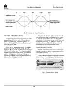
A correctly phased propeller shaft is one in which the
yoke bores or flange ears are in the same plane, Fig. 5.
Propeller shaft phasing affects joint cancellation in
that an incorrectly phased shaft will induce torsional
excitation (shaft windup and unwind).
It can be see in Fig. 4 that a propeller shaft is out of
phase any time that the slip joint yoke bore or flange ear
center line is rotated to any point between 0 and 180
degrees with respect to the yoke or flange at the
opposite end of the shaft.
Positioning the yoke at one
end of the shaft at 0 degrees and the slip joint yoke at 90
degrees results in a maximum out-of-phase condition
and torsional excitation will be greatest.
Drive line
vibration will be severe.
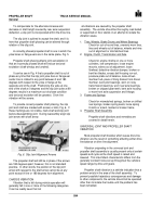
To provide correct propeller shaft phasing, the slip
joint and shaft are marked with arrows or dots, Fig. 6.
If
these markings are not visible, mark shaft and slip joint
before disassembling joint.
During reassembly align slip
joint arrow with shaft arrow.
Back to Top


