TM-5-3805-254-14-P-2 - Page 605 of 894
PROPELLER SHAFT
TRUCK SERVICE MANUAL
General
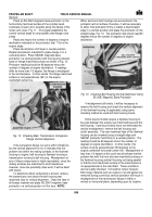
Place an SE-2067 magnetic base protractor on the
horizontally machined surface of the cylinder head,
crankcase oil pan rail or possibly along the flange of the
rocker arm cover, Fig. 11.
This angle establishes the
correct vertical angle for all propeller shaft flanges and
yokes.
Read and record the number of degrees of engine
declination indicated on the protractor dial.
This is the
engine angle.
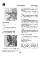
Place transmission shift lever in neutral position.
Rotate transmission mainshaft to place flange C in a
vertical position.
Place SE2067 magnetic base
protractor in a vertical position with one leg of protractor
base on flange machined surface as shown in Fig. 12.
Protractor reading should be 90 degrees minus the
number of degrees of engine declination.
If readings
differ by more than 1/2 degree, the flange is misaligned
in the vertical plane.
In other words, the flange machined
surface is not perpendicular (90°) to the engine
crankshaft center line.
Back to Top

