TM-5-3895-371-24-P - Page 182 of 330
TM 5-3895-371-24 & P
(20)
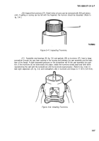
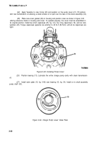
Inspect the trunnions (27). Small nicks or burrs can be removed with 500 grit emery
cloth. If galling or scoring can be felt with the fingernail, the trunnion should be discarded. (Refer to
fig. 3-41.)
Figure 3-41. Inspecting Trunnions.
(21)
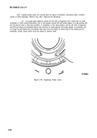
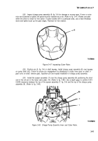
Assemble new bearings (29, fig. 3-4) and gaskets (28) on trunnions (27). Insert a large
screwdriver through the cam lever opening in the housing and between the cam assembly and the back
face of the flange. A slight downward pressure on the screwdriver will lift the cam assembly into posi-
tion. If the trunnions do not slide easily into place, rotate the trunnions slowly back and forth while
repositioning the cam with the screwdriver until the trunnions seat properly. (Refer to fig. 3-42). In-
stall eight capscrews (25, fig. 3-4) and lockwashers (26) in trunnions and torque to 11 lb-ft (14.9 N-m).
Figure 3-42. Installing Trunnions.
3-37
Back to Top


