TM-5-3895-372-10 - Page 12 of 184
TM 5-3895-372-10
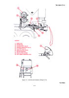
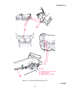
e. Controls and Indicators.
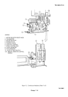
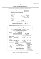
(1) Meter Register Reset Knob (Fig. 1-2, Sheet 1) - The reset knob is used to set the meter register reading
back to zero.
(2) Tachometer (Fig. 1-2, Sheet 1) - The tachometer shows operating speed of the mixer hydraulic oil pump.
During normal operation, the reading should be 1620-1720 rpm.
(3) Meter Register (Fig. 1-2, Sheet 1) - The meter register is a digital counter that registers 10 for each
revolution of the cement meter-feeder.
Normal speed of the cement meter-feeder is 14.2 RPM, therefore, the meter
register shows 142 for each minute of operation.
By dividing the meter count for a concrete placement by the known
meter count for one cubic yard of the concrete design being used, the number of yards of concrete dispensed can be
calculated.
(4) Bypass Valve (Fig. 1-2, Sheet 1) - The bypass valve regulates flow of hydraulic fluid and is used to slow the
mix-auger for washout.
Turn the valve handle counterclockwise to decrease speed of the auger.
Close the valve
(clockwise) during normal operation.
(5) Control Valve (Fig. 1-2, Sheet 1) -The control valve starts and stops the mixing auger.
Pull the lever
(rearward) to start the mixing auger and push the lever forward to stop the operation.
(6) Throttle Control (Fig. 1-2, Sheet 1) - The throttle control lever regulates the truck engine speed.
For
information on truck engine operation refer to TM 9-2320273-10.
The throttle control is adjusted to obtain the desired
mixer hydraulic oil pump speed as indicated on the mixer tachometer.
Pull the throttle control lever until it is against the
rear stop for minimum engine speed and push it against the front stop for maximum engine speed.
(7) Winch Control Box (Fig 1-2, Sheet 1) - The winch control box provides all controls for lowering and raising
the mixing trough.
Switches are labeled JOG, RAISE, and LOWER.
When the RAISE button is depressed, the mixing
trough moves upward until the button is released or it strikes a micro switch mounted in the raise circuit.
This micro switch
protects the mixing trough from damage, should the RAISE button be held depressed longer then necessary to reach the
"lock position" for the mixing trough.
To unlock the mixing trough, it is necessary to apply pressure in the raise direction
and depress the JOG button while unlatching the mixing trough.
After the mixing trough is unlatched depress the LOWER
button to lower the mixing trough to the desired position.
(8) Low-Flow Meter (Fig. 1-2, Sheet 1) - The low-flow meter functions in the same manner as the hi-flow meter
except that it regulates flow from the low-flow admix system.
(9) Hi-Flow Meter (Fig. 1-2, Sheet 1) - The hi-flow meter regulates the quantity of liquid admix from the hi-flow
system that is being mixed into the concrete batch.
The float valve in the sight glass is preset to the desired mix.
The hi-
flow lever sets the flow. Raise up on the lever to increase flow. Lower the lever to decrease or stop flow.
(10) Low-Flow and Hi-Flow Quick Acting Valves (Fig. 1-2, Sheet 1) - The quick acting valves open and close
automatically whenever the main clutch is engaged or disengaged.
If the quick-acting valve is closed you must hold it
open manually in order to operate the flowmeter lever for the system you are working with.
(11) Sand Dial (Fig.
1-2, Sheet 2) - The sand dial control wheel raises and lowers the sand gate, allowing more
or less sand to be added to the mix. A pointer is connected to the control wheel shaft and moves over the dial face as the
control wheel is turned.
The dial setting is obtained from the mix settings chart.
A stop screw locks the gate to prevent
movement after the setting is made.
Change 1 1-4
Back to Top

