TM-5-3895-372-10 - Page 13 of 184
TM 5-3895-372-10
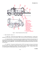
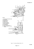
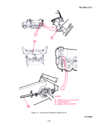
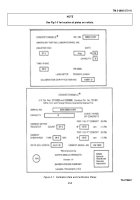
(12) Stone Dial (Fig. 1-2, Sheet 2) - The stone dial control wheel raises and lowers the stone gate to allow more
or less stone to be added to the mix.
A pointer is connected to the control wheel shaft and moves over the dial face as the
control wheel is turned.
The dial setting is obtained from the mix settings chart.
A stop screw locks the gate to prevent
movement after the setting is made.
(13) Air Shutoff Valve (Fig. 1-2, Sheet 2) - The air shutoff valve is an on/off valve for controlling air to the
vibrators, fluffer pads, and liquid admix system. Turn clockwise to close and counterclockwise to open.
(14) Screen Vibrator Valve (Fig. 1-2, Sheet 2) - The screen vibrator valve is an on/ off valve for controlling air to
cement vibrating screens. Turn clockwise to close and counterclockwise to open.
(15) Fluffer Valve (Fig. 1-2, Sheet 2) - The fluffer valve controls air to aerator pads in the bottom of the cement
bin. Depress the lever for about 10 seconds to "fluff" the cement in the bin.
The cement meter-feeder is calibrated for
fluffed cement and after road travel the cement tends to pack down.
(16) Main Clutch Lever - The main clutch lever engages the conveyor belt which runs under the sand and stone
bins. By engaging this lever, the operator brings sand and stone to the rear of the unit where it drops off the conveyor belt
into the mixing trough.
Simultaneously, an interlock causes the quick acting water and admixture valves to be opened.
Because the cement meter-feeder is mechanically driven by a roller chain from the rear conveyor belt shaft, cement is
automatically metered onto the sand and stone conveyor belt at the same time.
(17) Water Control (Fig. 1-2, Sheet 2) - The water control regulates the amount of water fed into the mix. Adjust
the pointer to the setting specified in the mix settings chart.
(18) Dry Admix Dog Clutch Lever (Fig. 1-2, Sheet 2) - This lever engages a clutch to feed dry admix into the
mixing trough and disengages the clutch to stop the flow of dry admix.
Push the lever left to engage the clutch and right to
disengage it.
(19) Dry Admix Control Dial (Fig. 1-2, Sheet 2) - The dry admix control dial regulates the amount of dry admix
that is added to the mix.
Adjustment to the amount of admix can be made by loosening the pointer knob and setting the
pointer at the setting specified on the mix settings chart.
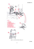
(20) Cement Bin Clutch Lever (Fig. 1-2, Sheet 3) - The lever engages and disengages the cement bin clutch
which provides power to the feeder mechanism.
To start feeding cement into the mix, push the lever to the left. To stop
feeding cement pull the lever to the right.
A locking arm is provided to lock the clutch in the engaged position.
Lift to
release the lock.
(21) Inclinometer (Fig. 1-2, Sheet 3) - The inclinometer indicates the degree of slant in the mixing trough.
In
normal operation, the slant is 15-25°.
If adjustment is required, operate the winch controls to raise or lower the mixing
trough.
(22)
Swivel Ring Lockarm (Fig. 1-2, Sheet 3) - The swivel ring lockarm prevents the swivel ring from turning
when in the up position. To rotate the swivel ring from 0° to 1700 push the lockarm down, then rotate the swivel ring so
that the trough is in the desired position, then raise up the lockarm.
(23)
Manual Vibrator Control Handle (Fig. 1-2, Sheet 1) - The manual vibrator control handle is connected to the
rear vibrator air valve.
It provides a means of manually "shaking" the aggregate bins should their contents become too
packed or the automatic controls fall.
Change 1 1-5
Back to Top


