TM-5-3895-372-20 - Page 250 of 694
TM 5-3895-372-20
ADMIX SYSTEMS
6-17. AIR RELIEF VALVE MAINTENANCE AND ADJUSTMENT (Continued).
LOCATION/ITEM
ACTION
REMARKS
15.
Relief valve (2).
Install on nipple (1).
Coat threads with liquid teflon.
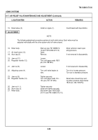
F. ADJUSTMENT.
NOTE
The following adjustment procedure pertains to both relief valves. Each valve must be
adjusted individually with the other system shut-off valve closed.
16.
Mixer body.
Start-up (see TM
3895372-
Allow vehicle to reach oper-
10 and TM 9-2320-273-10).
ating pressure.
17.
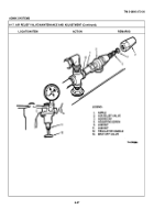
Air hutoff valve (13).
Open.
18.
Acor cap (3).
Remove.
If not removed in disassembly
19.
Jam nut (11).
Loosen.
20.
Regulator handle (12).
Turn until gage reads 1820
psi (124-138 kPa).
21.
Jam nut (5).
Loosen.
If not loosened in disassembly
22.
Adjusting screw (4).
Turn until valve begins to
Turn in to increas pressure.
vent.
Turn out to decrease pressure.
23.
Jam nut (5).
Tighten securely.
24.
Regulator handle (12).
Turn until gage reads 14½ -
Relief valve should stop vent-
15½ psi (100 107 kPa).
ing when pressure drops below
18-20 psi (124-138 kPa).
25.
Jam nut (1 1).
Tighten securely.
26.
Acorn cap (3).
Install and tighten securely.
27.
Mixer body.
Shut-down (see TM 9-2320-
273-10 and TM 5-3895-372-10).
6-56
Back to Top


