TM-5-3895-372-20 - Page 390 of 694
TM 5-3895-372-20
CEMENT SYSTEM.
8-10.
SCREEN VIBRATOR MAINTENANCE (Continued).
LOCATION/ITEM
ACTION
REMARKS
B.
INSTALLATION.
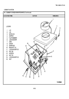
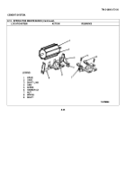
6. Gasket (12).
Position on bottom of
hopper (4).
7. Grommet (10) and
a.
Install grommet (10) into
arm (9).
hopper (4) as shown.
b.
Install arm (9) thru grom-
met (10) and secure inside
hopper at screen (13) with
screw (11), lockwasher (1),
flat washer (2) and nut (3).
8. Vibrator (6).
Aline with arm (9) and sec-
ure with screw (5), lockwasher
(1), flat washer (2), and nut (3).
9. Coupler (7).
Screw into vibrator (6).
10. Air line (8).
Twist and push onto coupler (7).
C.
OPERATIONAL CHECK
11. Air line (8).
a.
Use quick-disconnect fit-
ting to connect to supply
line (see TM 5-3895-372-10).
b.
Check for screen vibration.
NOTE
If screen does not vibrate, check for:
If screen does not vibrate, check for:
a.
Chassis air pressure less than 65 psi (448 kPa).
b.
Arm (9) broken or not bolted to screen.
c.
Unlubricated vibrator.
(Vibrator may rust due to moisture in air lines.)
d.
Blocked or leaking air lines.
8-26
Back to Top


