TM-5-3895-372-20 - Page 500 of 694
TM 5-3895-372-20
HYDRAULIC SYSTEM.
10-11.
RELIEF VALVE MAINTENANCE (Continued).
LOCATION/ITEM
ACTION
REMARKS
B.
INSTALLATION.
NOTE
Apply liquid teflon to threaded joints at installation.
4.
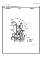
Relief valve (1).
Install in adapter (2).
5.
900 elbow (4).
Install.
6.
Swivel nut (3).
Install and tighten securely.
NOTE
Follow on maintenance action required: Fill oil reservoir; refer to LO 5-3895-372-12.
C.
OPERATIONAL CHECK.
NOTE
After installing a new relief valve,
always test and adjust to specifications For this procedure refer to
paragraph 1010.
10-30
Back to Top

