TM-5-3990-263-13-P - Page 29 of 728
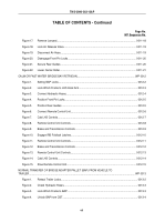
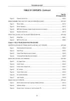
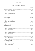
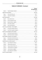
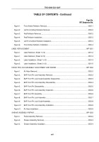
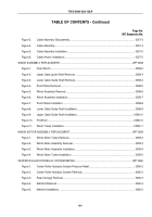
TABLE OF CONTENTS - Continued
Page No.
WP Sequence No.
Figure 1.
Front Amber Reflector Removal.
..........................................................................................
0050-1
Figure 2.
Left Front Amber Reflector Removal.
...................................................................................
0050-2
Figure 3.
Red Reflector Removal.
.......................................................................................................
0050-2
Figure 4.
Red Reflector Installation.
....................................................................................................
0050-3
Figure 5.
Left Front Amber Reflector Installation.
................................................................................
0050-3
Figure 6.
Front Amber Reflector Installation.
.......................................................................................
0050-4
LABEL REPLACEMENT.
.............................................................................................................................
WP 0051
Figure 1.
Label Removal. (Sheet 1 of 2) .
............................................................................................
0051-2
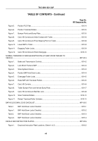
Figure 1.
Label Removal. (Sheet 2 of 2) .
............................................................................................
0051-3
Figure 2.
Label Installation. (Sheet 1 of 2) .
.........................................................................................
0051-4
Figure 2.
Label Installation. (Sheet 2 of 2) .
.........................................................................................
0051-5
FRONT PIN LOCK ASSEMBLY ADJUSTMENT AND REPAIR.
.................................................................
WP 0052
Figure 1.
Air Hose Removal.
...............................................................................................................
0052-2
Figure 2.
BAP Front Pin Lock Assembly Removal.
.............................................................................
0052-2
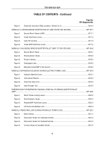
Figure 3.
BAP Front Pin Lock Guide Assembly Disassembly.
............................................................
0052-3
Figure 4.
BAP Front Pin Lock Assembly Disassembly.
.......................................................................
0052-4
Figure 5.
BAP Front Pin Disassembly.
................................................................................................
0052-5
Figure 6.
BAP Front Pin Lock Assembly Inspection.
...........................................................................
0052-6
Figure 7.
BAP Front Pin Assembly.
.....................................................................................................
0052-6
Figure 8.
BAP Front Pin Lock Assembly.
............................................................................................
0052-7
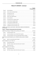
Figure 9.
BAP Front Pin Lock Guide Assembly.
..................................................................................
0052-8
Figure 10.
BAP Front Pin Lock Assembly Installation.
..........................................................................
0052-9
Figure 11.
Air Hose Installation.
............................................................................................................
0052-9
SHEAVE ASSEMBLY REPAIR.
...................................................................................................................
WP 0053
Figure 1.
Roller Assembly Removal.
...................................................................................................
0053-2
Figure 2.
Sheave Assembly Removal.
................................................................................................
0053-3
Figure 3.
Sheave Assembly Installation.
.............................................................................................
0053-4
TM 5-3990-263-13&P
xvii
Back to Top

