TM-5-3990-263-13-P - Page 31 of 728
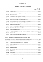
TABLE OF CONTENTS - Continued
Page No.
WP Sequence No.
Figure 3.
Cable Assembly Disassembly.
.............................................................................................
0057-3
Figure 4.
Cable Assembly.
..................................................................................................................
0057-4
Figure 5.
Cable Assembly Installation.
................................................................................................
0057-5
Figure 6.
Cable Anchor Installation.
....................................................................................................
0057-5
WINCH ASSEMBLY REPLACEMENT.
.......................................................................................................
WP 0058
Figure 1.
Drain Winch.
.........................................................................................................................
0058-2
Figure 2.
Upper Cable guide Shaft Removal.
......................................................................................
0058-3
Figure 3.
Lower Cable Guide Shaft Removal.
.....................................................................................
0058-4
Figure 4.
Pivot Plates Removal.
..........................................................................................................
0058-5
Figure 5.
Winch Assembly Removal.
...................................................................................................
0058-6
Figure 6.
Winch Assembly Installation.
................................................................................................
0058-7
Figure 7.
Pivot Plates Installation.
.......................................................................................................
0058-8
Figure 8.
Lower Cable Guide Shaft Installation.
..................................................................................
0058-9
Figure 9.
Upper Cable Guide Shaft Installation.
................................................................................
0058-10
Figure 10.
Fill Winch.
...........................................................................................................................
0058-10
Figure 11.
Winch Tubes Installation.
...................................................................................................
0058-11
WINCH MOTOR ASSEMBLY REPLACEMENT.
.........................................................................................
WP 0059
Figure 1.
Winch Motor Tubes Removal.
..............................................................................................
0059-2
Figure 2.
Winch Motor Assembly Removal.
........................................................................................
0059-3
Figure 3.
Winch Motor Assembly Installation.
.....................................................................................
0059-4
Figure 4.
Winch Motor Tubes Installation.
...........................................................................................
0059-5
CENTER ROLLER HYDRAULIC SYSTEM REPAIR.
..................................................................................
WP 0060
Figure 1.
Center Roller Hydraulic System Pressure Relief.
.................................................................
0060-2
Figure 2.
Center Roller Hydraulic System Removal.
...........................................................................
0060-2
Figure 3.
Rear Carriage Removal.
.......................................................................................................
0060-3
Figure 4.
Manifold Removal.
................................................................................................................
0060-4
Figure 5.
Manifold Installation.
.............................................................................................................
0060-5
TM 5-3990-263-13&P
xix
Back to Top

