TM-5-3990-263-13-P - Page 399 of 728
INSTALLATION - Continued
4.
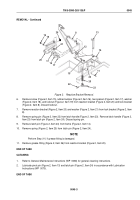
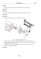
Using one hand to hold roller (Figure 2, Item 5) in alignment with shaft (Figure 2, Item 6), slide shaft (Figure
2, Item 6) through roller (Figure 2, Item 5). Ensure grease fitting (Figure 2, Item 8) and slot in shaft cap (Figure
2, Item 3) are facing out.
5.
Align slot in shaft (Figure 2, Item 6) with edge of roller housing (Figure 2, Item 4).
6.
Insert shaft cap (Figure 2, Item 3) in slot and align with holes in roller housing (Figure 2, Item 4).
7.
Insert two screws (Figure 2, Item 1) through two lockwashers (Figure 2, Item 2) and into roller housing (Figure
2, Item 4).
8.
Lubricate roller assembly
(WP
0070).
END OF TASK
END OF WORK PACKAGE
TM 5-3990-263-13&P
0046
0046-3/4 blank
Back to Top

