TM-5-3990-263-13-P - Page 435 of 728
REMOVAL - Continued
19
18
20
19
14
4
9
11
13
17
10
15
15
16
11
12
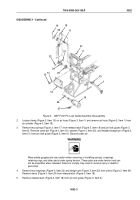
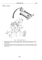
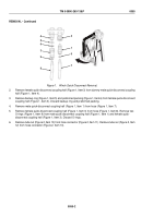
Figure 2.
Sheave Assembly Removal.
4.
Remove cotter pin (Figure 2, Item 13) from pulley pin (Figure 2, Item 14). Remove pulley pin (Figure 2, Item
14), two spacers (Figure 2, Item 15), and pulley (Figure 2, Item 16) from winch frame (Figure 2, Item 4). Discard
cotter pin.
5.
With the aid of an assistant, remove cotter pin (Figure 2, Item 17) from roller pin (Figure 2, Item 18). Remove
roller pin (Figure 2, Item 18), two spacers (Figure 2, Item 19), and roller assembly (Figure 2, Item 20) from
winch frame (Figure 2, Item 4). Discard cotter pin.
END OF TASK
CLEANING
1.
Refer to General Maintenance Instructions (WP
0038) for general cleaning instructions.
2.
Lubricate parts in accordance with Lubrication Instructions (WP
0070).
END OF TASK
INSPECTION
Refer to General Maintenance Instructions (WP
0038) for general inspection instructions.
END OF TASK
TM 5-3990-263-13&P
0053
0053-3
Back to Top

