TM-5-3990-263-13-P - Page 443 of 728
FIELD MAINTENANCE
WINCH HYDRAULIC SYSTEM REPLACEMENT
INITIAL SETUP:
Tools and Special Tools
Pan, Drain, 5-Gallon (WP
0078, Table 2, Item 1)
Tool Kit, General Mechanics: Automotive
(WP
0078, Table 2, Item 2)
Materials/Parts
Grease (WP
0081, Table 1, Item 10, 11, 12, 13,
14)
Backup Ring (WP
0082, Table 1, Item 7) Qty:
1
Preformed Packing (WP
0082, Table 1, Item 8)
Qty:
1
O-ring (WP
0082, Table 1, Item 22) Qty:
2
Preformed Packing (WP
0082, Table 1, Item 14)
Qty:
2
Preformed Packing (WP
0082, Table 1, Item 13)
Qty:
1
Materials/Parts (cont.)
Lockwasher (WP
0082, Table 1, Item 43) Qty:
2
Preformed Packing (WP
0082, Table 1, Item 17)
Qty:
2
Lockwasher (WP
0082, Table 1, Item 46) Qty:
2
References
Parts Manual (WP
0073, Figure 12)
Parts Manual (WP
0073, Figure 14)
Parts Manual (WP
0073, Figure 17)
Equipment Condition
Load removed from the BAP. (WP
0008)
BAP removed from the CBT. (WP
0006)
REMOVAL
CAUTION
Do not remove tube nuts and flared tube sleeves from hydraulic tubes unless there is leakage
or other damage to tubes, tube nuts, or flared tube sleeves that make them unserviceable.
NOTE
•
Use a drain pan to catch fluid draining from hoses and fittings. Wipe up any spillage with
a rag. Handle, store, and dispose of drained fluids in accordance with local policies and
procedures.
•
Tag all hoses and tubes before disconnecting. Note if each hose or tube has a male or
female connector.
1.
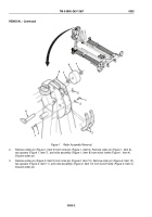
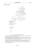
Remove male quick-disconnect coupling half (Figure 1, Item 1) from dummy female quick-disconnect coupling
half (Figure 1, Item 2).
TM 5-3990-263-13&P
0055
0055-1
Back to Top


