TM-5-3990-263-13-P - Page 450 of 728
INSTALLATION - Continued
37
38
39
41
28
42
43
18
40
45
44
46
47
48
49
51
50
56
57
58
52
63
54
53
60
59
55
62
61
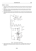
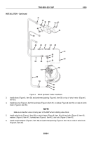
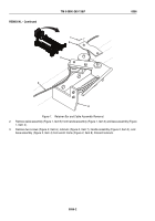
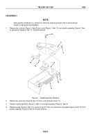
Figure 6.
Winch Hydraulic Tubes Installation.
3.
Install elbow (Figure 6, Item 56) and preformed packing (Figure 6, Item 58) on top of winch motor (Figure 6,
Item 53).
4.
Install tube nut (Figure 6, Item 50) and tube (Figure 6, Item 51) on elbow (Figure 6, Item 52) on side of winch
motor (Figure 6, Item 53).
NOTE
Make sure breather valve is facing rear of the BAP when installing valve block.
5.
Install valve block (Figure 6, Item 28) on winch frame (Figure 6, Item 18) with two bolts (Figure 6, Item 40),
washers (Figure 6, Item 41), lockwashers (Figure 6, Item 42), and nuts (Figure 6, Item 43).
6.
Install straight adapter (Figure 6, Item 38) and preformed packing (Figure 6, Item 39) on side of valve block
(Figure 6, Item 28).
TM 5-3990-263-13&P
0055
0055-8
Back to Top

