TM-5-3990-263-13-P - Page 458 of 728
DISASSEMBLY
NOTE
Note quantity of threads on u-bolt prior to removing locknuts and jam-nuts to ensure proper
tension on spring during installation.
1.
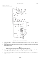
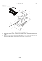
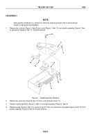
Remove two locknuts (Figure 3, Item 9) and u-bolt (Figure 3, Item 10) from handle assembly (Figure 3, Item
3) and spring (Figure 3, Item 11). Discard locknuts.
11
10
12
14
15
9
3
4
13
Figure 3.
Handle Assembly Removal.
2.
Remove two jam-nuts (Figure 3, Item 12) from u-bolt (Figure 3, Item 10).
3.
Remove handle assembly (Figure 3, Item 3) from base assembly (Figure 3, Item 4).
4.
Remove screw (Figure 3, Item 13), locknut (Figure 3, Item 14), and torsion lock plate (Figure 3, Item 15) from
handle assembly (Figure 3, Item 3). Discard locknuts.
TM 5-3990-263-13&P
0056
0056-4
Back to Top


