TM-5-3990-263-13-P - Page 497 of 728
FIELD MAINTENANCE
TRANSLOAD ROLLER HYDRAULIC SYSTEM REPAIR
INITIAL SETUP:
Tools and Special Tools
Pan, Drain, 5-Gallon (WP
0078, Table 2, Item 1)
Tool Kit, General Mechanics: Automotive
(WP
0078, Table 2, Item 2)
Materials/Parts
Grease (WP
0081, Table 1, Item 10, 11, 12, 13,
14)
Lubricating Oil (WP
0081, Table 1, Item 17, 18, 19,
20)
Rag (WP
0081, Table 1, Item 21)
Tape, Antiseizing (WP
0081, Table 1, Item 23)
Lockwasher (WP
0082, Table 1, Item 42) Qty:
1
Lockwasher (WP
0082, Table 1, Item 39) Qty:
2
O-ring (WP
0082, Table 1, Item 21) Qty:
2
Materials/Parts (cont.)
Lockwasher (WP
0082, Table 1, Item 43) Qty:
4
Lockwasher (WP
0082, Table 1, Item 50) Qty:
6
Lockwasher (WP
0082, Table 1, Item 41) Qty:
3
References
Parts Manual (WP
0073, Figure 8)
Parts Manual (WP
0073, Figure 22)
Parts Manual (WP
0073, Figure 23)
WP
0062
Equipment Condition
Load removed from the BAP. (WP
0008)
BAP unloaded from the CBT. (WP
0006)
REMOVAL
NOTE
•
Use a drain pan to catch fluid draining from hoses and fittings. Wipe up any spillage with
a rag. Handle, store, and dispose of drained fluids in accordance with local policies and
procedures.
•
Procedures for the curb-side and road-side transload roller guard plates and hydraulic
cylinders, hoses, and fittings are the same, except as otherwise noted.
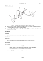
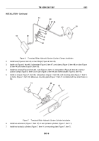
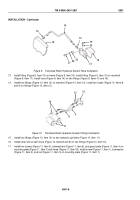
1.
Remove screw (Figure 1, Item 1), lockwasher (Figure 1, Item 2), and nut (Figure 1, Item 3) from guard plate
(Figure 1, Item 4). Remove two screws (Figure 1, Item 5) and lockwashers (Figure 1, Item 6) from guard plate
(Figure 1, Item 4) and mounting plate (Figure 1, Item 7). Discard lockwashers.
TM 5-3990-263-13&P
0061
0061-1
Back to Top


