TM-5-3990-263-13-P - Page 489 of 728
FIELD MAINTENANCE
CENTER ROLLER HYDRAULIC SYSTEM REPAIR
INITIAL SETUP:
Tools and Special Tools
Pan, Drain, 5-Gallon (WP
0078, Table 2, Item 1)
Tool Kit, General Mechanics: Automotive
(WP
0078, Table 2, Item 2)
Materials/Parts
Rag (WP
0081, Table 1, Item 21)
Lockwasher (WP
0082, Table 1, Item 42) Qty:
1
Lockwasher (WP
0082, Table 1, Item 50) Qty:
2
Lockwasher (WP
0082, Table 1, Item 43) Qty:
2
O-ring (WP
0082, Table 1, Item 21) Qty:
1
Lockwasher (WP
0082, Table 1, Item 41) Qty:
2
References
Parts Manual (WP
0073, Figure 4)
References (cont.)
Parts Manual (WP
0073, Figure 8)
Parts Manual (WP
0073, Figure 22)
Parts Manual (WP
0073, Figure 23)
WP
0038
Equipment Condition
Load removed from the BAP. (WP
0008)
BAP unloaded from the CBT. (WP
0006)
REMOVAL
NOTE
Use a drain pan to catch fluid draining from hoses and fittings. Wipe up any spillage with a
rag. Handle, store, and dispose of drained fluids in accordance with local policies and
procedures.
1.
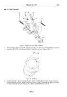
To relieve pressure from center roller hydraulic system, move hydraulic hand pump selector lever (Figure 1,
Item 1) down, in TRANSLOAD position, and pump hand pump lever (Figure 1, Item 2) until two transload
cylinders (Figure 1, Item 3) are fully extended.
TM 5-3990-263-13&P
0060
0060-1
Back to Top


