TM-5-4210-249-13-P-4 - Page 173 of 1012
TM 5-4210-249-13&P-4
0585-1
DRAFT
0585
FIELD LEVEL MAINTENANCE
HYDRAULIC GENERATOR DIGITAL DISPLAY MODULE REPLACEMENT
INITIAL SETUP:
REMOVAL
1.
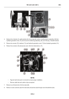
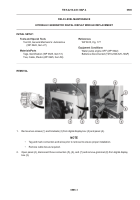
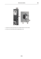
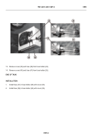
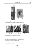
Remove two screws (1) and brackets (2) from digital display box (3) and panel (4).
NOTE
•
Tag and mark connectors and wires prior to removal to ensure proper installation.
•
Remove cable ties as required.
2.
Open panel (4), disconnect three connectors (5), (6), and (7) and remove grommet (8) from digital display
box (3).
-
-
-
-
-
-
-
-
-
-
-
-
-
-
-
-
-
-
-
-
-
-
-
-
-
-
-
-
-
-
-
-
-
-
-
-
-
-
-
-
-
- -
-
-
-
-
-
-
-
-
-
-
-
-
-
-
-
-
-
-
-
-
-
-
-
-
-
-
-
-
-
-
-
-
-
-
-
-
-
-
-
-
-
-
-
-
-
-
-
TFFT769
Tools and Special Tools
Tool Kit, General Mechanic’s: Automotive
(WP 0622, Item 27)
Materials/Parts
Tags, Identification (WP 0625, Item 51)
Ties, Cable, Plastic (WP 0625, Item 58)
References
WP 0615, Fig. 177
Equipment Conditions
Water pump engine OFF (WP 0022)
Batteries disconnected (TM 9-2320-325-14&P)
Back to Top


