TM-5-5420-202-10 - Page 390 of 535
0058
TM 5-5420-202-10
INSTALLATION
Fender and Shield
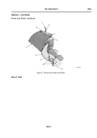
1. Install fender (Figure 3, Item 9) and shield (Figure 3, Item 8) on support bracket (Figure 3, Item 3).
2. Install three f at washers (Figure 3, Item 2) and new self-locking nuts (Figure 3, Item 1) on support bracket studs
(Figure 3, Item 4). Hand-tighten self-locking nuts.
3. Install two screws (Figure 3, Item 7), four f at washers (Figure 3, Item 6), and two new self-locking nuts
(Figure 3, Item 5) in shield (Figure 3, Item 8). (If necessary, align holes with cross-tip screwdriver). Hand-tighten
screws.
Figure 3.
Installing Fender and Shield.
Fender Angle
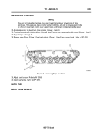
1. Position angle (Figure 4, Item 11) in place against fender (Figure 4, Item 3).
2. Install eight bolts (Figure 4, Item 4), sixteen f at washers (Figure 4, Item 5), eight new lockwashers
(Figure 4, Item 6), and eight new self-locking nuts (Figure 4, Item 7) in fender (Figure 4, Item 3) and angle
(Figure 4, Item 11). (If necessary, align holes with cross tipped screwdriver). Hand-tighten bolts.
3. Open rear fender stowage box cover (Figure 4, Item 2).
4. Install four bolts (Figure 4, Item 12), eight spacers (Figure 4, Item 10), four new lockwashers (Figure 4, Item 9),
and four new self-locking nuts (Figure 4, Item 8) in stowage box (Figure 4, Item 1). Hand-tighten bolts.
5. Use open end wrench and ratchet and socket to tighten bolts (Figure 4, Item 4).
6. Use open end wrench and ratchet and socket to tighten bolts (Figure 4, Item 12).
7. Use open end wrench and ratchet and socket to tighten nuts (Figure 4, Item 7 and Item 8).
8. Close rear fender stowage box cover (Figure 4, Item 2).
0058-4
END OF TASK
Back to Top


