TM-5-5420-203-14 - Page 206 of 298
TM 5-5420-203-14
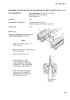
FAR-SHORE CENTER SECTION TRANSVERSE BRACE REPLACEMENT (Sheet 2 of 4)
e.
f.
Remove two retainers (7) from one
side of two pins (8) holding cable
retainer (9) in position on quadrant (5).
Remove two pins (8) from flanges
(10) of quadrant (5) releasing cable
retainer (9)
0
Remove cable retainer (9) holding
cables (11) in grooves of quadrant (5).
h.
i.
1.
The scissoring cables are heavy and
can crush you. Stay clear of the cables
when they are suspended.
NOTE
The direction of the rotation of the cable
strands are critical. The left cable is not
designed for use on the right and vice
versa. Note the rotation of the stands of the
cable when replacing cables, check the
current placement with illustrations given
and ensure they are installed properly.
Attach a lifting sling to the approximate
center of the cables (11) and lift until slack
is removed.
Remove equalizer plate pin retainer (12)
plate (14) in position in cable beam (15).
NOTE
Have a second crew member steady the
cables/equalizer plate for the following step.
Remove equalizer plate pin (13) from cable
beam (15) releasing equalizer plate (14).
Remove retainer (16) securing nut (17) to bolt
(18). Remove nut (17) from bolt (18)
quadrant strut (19) to cable beam (15)
bolt (18).
Repeat for second strut (20).
securing
. Remove
3-40
Back to Top


