TM-5-5420-203-14 - Page 209 of 298
TM 5-5420-203-14
QUADRANT REPLACEMENT
TOOLS/EQUIPMENT
SUPPLIES:
EQUIPMENT CONDITIONS:
PERSONNEL:
REMOVAL
REMOVE QUADRANT (4).
a.
b.
c.
d.
e.
f.
g.
(Sheet 1 of 3)
General Mechanics Tool Box SC 5180-90-N26
Lifting Device (2000 lbs capacity)
Sling, Multiple Leg
None.
Scissoring Cables and attaching hardware removed (pg 3-20).
Hydraulic Cylinder removed (pg 3-23).
Flexible Hydraulic Lines removed (pg 3-32).
Four
NOTE
Some quadrants may be equipped with a modification using a quadrant locking pinto hold
a second locking pin in position. See Detail A. Illustration is shown with modification to
quadrant Perform the procedures that apply.
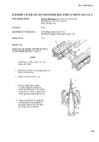
Attach a lifting sling (1) through the top
hole in the center of the quadrant (4).
Attach sling (1) to lifting device cable (2).
Place a wood block (3) used as a scotch
under the near-shore bottom end of the
quadrant (4) as shown.
Remove slack from lifting sling (l).
Remove bridge pin retainer (5)
(see Detail A) from quadrant locking
pin (6). Remove quadrant locking pin
(6) from angular plates (7).
Remove bridge pin retainer (8)
(see Detail B), from quadrant
locking pin (9). Refer to Detail A.
Remove second quadrant locking
pin (9) from opposite side of
quadrant (4) and quadrant hinge
pin (10).
Perform steps d. and e. for other
side of quadrant (4).
Refer to Detail B. Remove bridge pin retainer
(11) from quadrant locking pin (12). Remove
quadrant locking pin (12) from quadrant
hinge (13).
3-43
Back to Top


