TM-5-5420-228-24 - Page 307 of 750
TM 5-5420-228-24
OVERHEAD CYLINDER RELIEF VALVE (RV9) AND FLOW REGULATOR (PCV1)
REPLACEMENT (Sheet 1 of 4)
PROCEDURE INDEX
PROCEDURE
PAGE
Removal
3-110
Installation
3-112
TOOLS:
12 in. adjustable wrench (2) SUPPLIES:
Pipe tape (Item 19, Appendix D)
1-1/8 in. open end wrench
Masking tape (Item 18, Appendix D)
1-1/4 in. open end wrench
Pencil (Item 22, Appendix D)
1-3/8 in. open end wrench
Drip pan (suitable containers)
15 in. adjustable wrench
Rags (Item 12, Appendix D)
REMOVAL:
Protective caps and plugs
REFERENCES:
(LO 5-5420-202-12).
PRELIMINARY PROCEDURES:
Remove overhead cylinder armor (page 3-223)
Relieve hydraulic pressure (page 3-71)
NOTE
Use rags and drip pans to catch excess hydraulic fluid. Use
masking tape to tag lines for installation. Cap or plug all lines and
fittings as they are disconnected.
Lay hose assemblies aside, as they are disconnected, to provide
clear work area around relief valve (RV9) and connected parts.
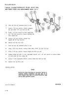
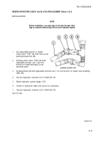
1.
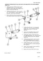
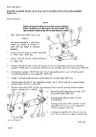
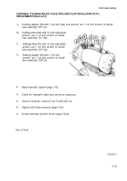
Holding adapter (A) with 1-1/8 inch wrench, use 1-1/4 inch wrench to remove hose assembly
“CM” (B).
Go on to Sheet 2
TA251508
3-110
Back to Top

