TM-55-1425-289-14
TM-55-1425-289-14 - Page 34 of 61
TM 55-1425-289-14
Table 5-7.
Continued
Item
No. Required
Application
C
(cont)
and nail to the semitrailer floor through the
2- x 4- x 36-inch piece with five 20d nails in
a staggered pattern. Nail the other 2- x 4- x
36-inch piece to the one below in a like man-
ner with five 30d nails.
D
4
Chains, load-lashing.
Attach to the front and
rear tiedown provisions on the vehicles and
semitrailer as indicated. Substitute, if de-
sired, 112- or 5/8-inch IWRC wire rope in a
complete loop, and secure with four cable
clips spaced about 4 inches apart.
E
4
Load binders.
Secure grabhooks to chains,
and take up slack with eccentric takeup.
Grabhooks are not required if wire rope and
cable clips are used.
Table 5-8.
Application of Materials for Blocking and
Tiedown of an S280 Shelter, with OMTS, on
Semitrailer (Fig 5-6)
Item
No. Required
Application
A
2
End blocks. Each to consist of one piece of 4-
x 4- x 48-inch lumber.
Center and place
each piece against the end of the shelter, and
nail to the floor with eight 60d nails. Nail
the lower 2- x 4- x 48-inch piece to the 4- x
4- x 48-inch piece with eight 30d nails. Nail
the upper 2- x 4- x 48-inch piece to the low-
er piece with eight 20d nails. If the trailer or
truck is equipped with a headboard, the for-
ward end block should be placed prior to
loading the shelter on the trailer or truck.
Table 5-8.
Continued
Item
No. Required
Application
B
4
Side blocks. Each to consist of one piece of 4-
x 4- x 36-inch lumber and two pieces of 2-
x 4- x 36-inch lumber. Place the 4- x 4- x
36-inch piece on the floor and against the
shelter about 18 inches in from the end of
the shelter.
Nail to the floor with six 60d
nails. Nail the lower 2- x 4- x 36-inch piece
to the 4- x 4- x 36-inch piece with six 30d
nails.
Nail the upper 2- x 4- x 36-inch piece
to the lower 2- x 4- x 36-inch piece with six
30d nails.
C
8
Tiedowns. Each to consist of one piece of
wire rope, 3/8-inch, 6 x 19, IWRC, length as
required. Form a complete loop between the
tiedown provision and the appropriate
trailer stake pocket at a maximum angle of
450. Wire-rope ends should overlap approx-
imately 24 inches.
D
48
Clamps. Place four on each item E at the
overlapped area.
Space clamps 3-1/2 inches
apart, with a minimum of 6 inches from the
ends of the wire rope.
Place one clamp on
each thimble, item G, to secure the thimble
to the wire rope at the trailer stake pockets
and at the equipment tiedown provisions.
E
16
Thimbles. Locate one under the wire rope at
each place where the wire rope passes
through the equipment tiedown provisions
and over the edge of the trailer stake
pockets.
Secure each thimble to the wire
rope with one 3/8-inch clamp.
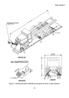
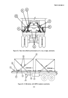
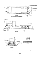
Figure 5-4.
Blocking and tiedown of M35 truck on 12-ton, or larger, semitrailer.
5-7
Back to Top

