TM-55-1425-289-14
TM-55-1425-289-14 - Page 36 of 61
TM 55-1425-289-14
CHAPTER 6
MARINE AND TERMINAL TRANSPORTABILITY GUIDANCE
Section I.
General
6-1.
Scope
This
chapter
provides
marine
and
terminal
transportability guidance for movement of the ROLAND
missile system.
It covers technical and physical
characteristics, as well as safety considerations, and
prescribes the materials and guidance required to
prepare, load, tie down, and unload the system
equipment.
6-2.
Safety
In addition to the safety precautions contained in
chapter 3, the following areas should be noted as
applicable:
a.
If ammunition or explosives are to be
transported with the ROLAND missile system, the
activity offering the cargo for transport will notify the
carrier in compliance with paragraph 2-7, AR 55-228.
b.
Ammunition, explosives, and vehicles will be
handled and stowed in accordance with provisions
contained Water Carrier Tariff No.
31 and Title 46/Title
49, Code of Federal Regulations.
c.
Fire extinguishers must be available during all
loading and unloading operations.
d.
Vehicle fuel tanks must not be more than one
fourth full.
6-3.
Water Shipment
The ROLAND missile system can be transported by a
great variety of inland-waterway cargo carriers and
lighters and by all seagoing cargo vessels.
NOTE
In
this
chapter,
the
methods
described for lifting and securing
vehicles
are
recommended
procedures.
Other methods of
handling and stowing may be used
provided they will ensure safe
delivery without damage.
Section II.
LOADING AND SECURING
6-4.
General Rules for Stowing
a.
General.
Whenever possible, ROLAND missile
system components should receive the protection of
below-deck stowage.
In general, good stowage of
vehicles means vehicles are placed fore and aft as
close together as practicable with minimum spacing
between outer vehicles and the sweatboard.
Breakable
parts are protected, and spare parts are located within or
near the vehicles.
Vehicles are stowed in neutral with
brakes set, battery terminals disconnected, and fuel
drained, and secured with adequate blocking and
lashing.
Securing includes blocking of wheels on all four
sides so that the vehicles cannot move in any direction;
bracing of individual vehicle blocks to bulkheads,
stanchions, and other vehicle blocks; and lashing of
vehicle with wire rope or chain.
NOTE
Department
of
Transportation
exemption (DOT-E-7280) authorizes
DOD to ship vehicles with fuel tanks
three-quarters full when vehicles are
loaded
on
vessels
that
are
adequately ventilated by power
blowers, such as the roll-on/roll-off
vessels.
b.
Loading.
Vehicles are always loaded onto
vessels in their minimum configuration; that is, reduced
height, width, and length and with or without cargo.
The
vehicles can be driven or lifted by crane of adequate
capacity onto landing craft, beach discharge and
amphibious lighters, and landing ship tanks.
They can
also be driven onto the decks or barges from a pier
when tidal conditions are suitable and ramps are
available.
The vehicles and the fire unit can be lifted by
shoreside or floating cranes of adequate capacity onto
seagoing vessels.
Jumbo booms and heavy-lift ship's
gear may be used in loading vehicles and other cargo
onto vessels.
The vehicles can be driven or towed onto
roll-on/roll-off vessels.
The ROLAND fire unit and the
XM1058 truck transporter may be loaded as a single unit
or as separate items, based on the type of vessel and
the stowage location available.
The M35 truck
transporting an OMTS shelter may be loaded as a single
unit or as separate items.
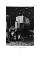
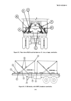
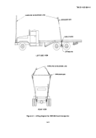
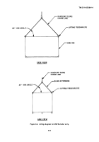
Typical lifting diagrams for
ROLAND missile system components are shown in
figures 6-1 through 6-4.
c.
Tiedown.
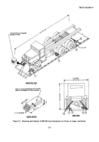
Typical blocking and tiedown details for
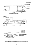
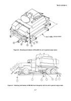
ROLAND missile system components are shown in
figures 6-5 through 6-8.
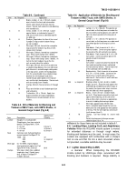
Materials and their application
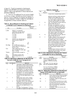
are listed in tables 6-1 through 6-6.
NOTE
Figure 6-5 was extracted from US
Army Materiel Command drawings.
Reference to page numbers in the
notes within this figure refer to the
number listed in the lower left-hand
corner of the figure.
6-1
Back to Top


