TM-55-1425-289-14
TM-55-1425-289-14 - Page 44 of 61
TM 55-1425-289-14
Table 6-4.
Continued
Item
No. Required
Application
B
4
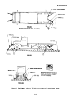
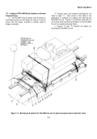
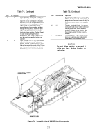
Blocks, lumber, 4- x 6- x 120-inch. Locate
one in front of the front and intermediate
wheels and in back of the front and rear
wheels. Toenail each end to the side blocking
with two 60d nails.
C
8
Cleats, lumber, 4- x 6- x 18-inch.
Locate
against blocks as indicated in figure 6-7,
and secure each cleat to side blocking with
ten 60d nails.
D
8
Padeyes. Required on the floor of the vessel
if proper D-rings or deck tiedown fittings
are not available.
E
2
Wire rope, 5-8-inch, formed into a complete
loop around the tiedown ring. Secure with
clamps (item I below).
F
2
Wire rope, 518-inch, formed into a complete
loop.
Secure with clamps (item I below).
G
2
Wire rope, 518-inch, formed into a complete
loop.
Secure with clamps (items I below).
At-
tach to the front tiedown ring on the fire
unit, on each side of the vehicle.
H
2
Wire rope, 5/8-inch; form the first cable into
a complete loop between the rear right-hand
golf club clevis, routed through cable guides
at the top corner, and the left-hand padeye;
form the second cable into a complete loop
between the left-hand golf club clevis,
routed through cable guides at the top cor-
ner, and the right-hand padeye.
Secure each
with four clamps (item I below).
I
28
Clamps, 5/8-inch. Secure to items E through
H.
J
16
Place one thimble at each tiedown provision
and turnbuckle.
K
8
Turnbuckles, 3/4- x 18-inch.
Apply turn-
buckles between wire rope and padeyes.
Tighten to even tension between all turn-
buckles.
Table 6-5.
Bill of Materials for Blocking and
Tiedown of M35 Truck, with OMTS Shelter, in
General Cargo Vessel (Fig 6-8)
Approximate
Item
Description
Quantity
Lumber
Douglas-fir, or comparable:
Straight-grain, free from material
defects; Fed Spec MM-L-751H:
2- x 4-inch
8 linear ft
2- x 12-inch
44 linear ft
4- x 6-inch
62 linear ft
Nails
Common steel; flathead; bright or
cement-coated; Fed Spec FF-N-
105B:
12d
32
30d
as required
60d
16
Wire rope
6 x 19, IWRC; improved plow
steel; preformed, regular-lay; Fed
Spec RR-W-410C: 5/8-inch
80 ft
Clamps
Wire rope, U-bolt clips, saddled,
single-grip; steel, Crosby heavy-
duty, or equal; Fed Spec FF-
C-450D: 5/8-inch
16
Table 6-6.
Application of Materials for Blocking and
Tiedown of M35 Truck, with OMTS Shelter, in
General Cargo Vessel (Fig 6-8)
Item
No. Required
Application
A
4
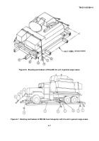
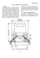
Lumber, 2- x 12- x 96-inch.
Pre-position on
vessel deck so that two pieces are under the
left rear wheels and two pieces are under the
right rear wheels parallel to the long axis of
the truck.
B
4
Lumber, 2- x 12- x 36-inch. Pre-position on
vessel deck so that two pieces are under each
front wheel parallel to the long axis of the
truck.
C
2
Side blocks.
Each to consist of 4- x 6- x
108-inch lumber.
Center one piece against
the outside of the left and right rear wheels.
D
2
Side blocks.
Each to consist of 4- x 6- x 48-
inch lumber.
Center one piece against the
outside of each front wheel.
E
4
End blocks.
inch lumber.
Locate one piece forward of the
front and intermediate wheels and behind
the front and rear wheels.
Toenail each end
of the side block with two 60d nails.
F
8
Backup cleats.
Each to consist of one piece
of 2- x 4- x 12-inch lumber.
Locate one on
top of items C and D against the joint of
each item E.
Nail to items C and D with four
12d nails per block.
G
as required
Bracing, lumber, 4-inch x 6-inch x random
length, cut-to-fit.
Place the ends against the
side blocking and blocking of other cargo, or
the side of the ship or other ship's structure.
Nail with 30d nails where appropriate.
H
as required
Blocks.
4-inch x 6-inch x random length,
cut-to-fit.
Place blocks around the truck and
against other blocking, on the side of the
ship or other ship's structure as appropriate,
to assist in holding the bracing in place.
J
4
Wire rope, approximately 20 feet each.
Form a complete loop through the truck tie-
down provision and appropriate deck padeye
or D-ring.
Pull the wire rope taut and secure
it with clamps (item K).
K
16
Clamps.
Use four clamps to
secure each
item
J.
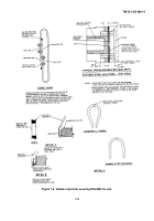
Details for placement of clamps are pro-
vided in figure 5-3 or 7-4.
Material for these items are not included in table 6-1.
6-6.
Landing Ships, Landing Craft, and Amphibious
Vehicles
When the ROLAND missile system is moved
for extended distances or through rough waters,
blocking and tiedowns must be used.
In most cases, the
vessels are equipped with turnbuckles with a sheep's
foot on one end that fits into a deck cloverleaf; where
not provided, a suitable substitute may be used.
6-7.
Lighter Aboard Ship (LASH)
a.
General.
When transporting the ROLAND
missile system by LASH-type ships, securement with
blocking and tiedowns is required.
Barge stability is
6-9
Back to Top


