TM-55-1425-289-14
TM-55-1425-289-14 - Page 46 of 61
TM 55-1425-289-14
CHAPTER 7
RAIL TRANSPORTABILITY GUIDANCE
Section I.
GENERAL
7-1.
Scope
This chapter provides rail transportability guidance for
movement of the ROLAND missile system.
It covers
technical and physical characteristics, as well as safety
considerations, and prescribes the materials and
guidance required to prepare, load, tie down, and unload
the vehicles.
7-2.
Maximum Utilization of Railcars
Additional cargo, as approved by the activity offering the
items for transport, may be transported with the
vehicles.
Section II.
TRANSPORT ON CONUS RAILWAYS
7-3.
General
The transportability guidance contained in this section is
applicable when the ROLAND missile system is
transported on CONUS railways.
The ROLAND fire unit
and the XM1058 truck transporter must be transported
as separate components.
The ROLAND missile system
does not exceed width limits for unrestricted movement
in its reduced configuration.
7-4.
Preparation for Loading
a.
ROLAND Missile System.
Preparation of the
ROLAND missile system will vary among loads to be
transported over various routes on different equipment,
including rail equipment, and with different restraint
procedures as identified in paragraphs 7-5 through 7-8.
b.
Rail Shipment Only.
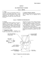
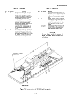
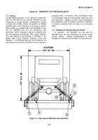
Rear-door structural support
must be installed prior to rail shipment.
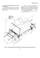
A diagram of a
rear entry door opening is shown in figure 7-1.
c.
Whip Antennae.
The whip antennae must be folded
and secured to avoid damage.
Procedures for folding
and securing the antennae are contained in TM 9-1425-
625-10.
Figure 7-1.
Diagram of rear entry door opening.
7-1
Back to Top

