TM-9-1200-215-34-P - Page 18 of 266
TM 9–1200–215–34&P
1–6
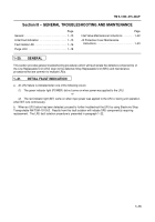
Section
II – EQUIPMENT DESCRIPTION AND DA
TA
Page
Page
Equipment Characteristics, Capabilities,
and Features
1–6
. . . . . . . . . . . . . . . . . . . . . . . . . . . . .
Location and Description of Major
Components
1–8
. . . . . . . . . . . . . . . . . . . . . . . . . . . . .
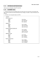
Differences Between Models
1–13
. . . . . . . . . . . . . . .
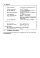
Equipment Data
1–13
. . . . . . . . . . . . . . . . . . . . . . . . . .
Equipment Configuration
1–14
. . . . . . . . . . . . . . . . . .
1–15.
EQUIPMENT CHARACTERISTICS, CAPABILITIES, AND FEATURES
a.
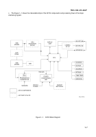
The Automatic Fire Control System (AFCS) components interface together with an on–board vehicle position
sensing system and hydraulic servo valves to automatically lay gun position.
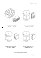
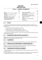
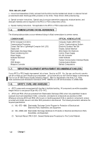
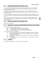
AFCS components include:
D
AFCS Computer Unit (ACU)
D
Display Unit (DU)
D
Vehicle Motion Sensor (VMS) Modem
D
Power Conditioning Unit (PCU)
(1)
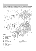
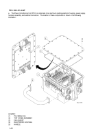
The AFCS Computer Unit (ACU) receives vehicle position data from the on–board positioning system for
ballistic computations, weapons control, and calculates distance and direction to the target location entered from
the Display Unit (DU).
Using stored ballistic data, the ACU calculates appropriate gun tube elevation to reach the
target.
Elevation and azimuth commands are sent to the weapon’s hydraulics system to adjust gun tube direction
and elevation.
The ACU automatically performs radio interface functions for the system.
It controls radios, radio network
interface, intercom interface, and composition/decomposition of messages.
It is the digital processing device for
the DU, interfaces with the on–board vehicle positioning system, and contains the embedded trainer controller for
simulating navigation and gun laying missions.
(2)
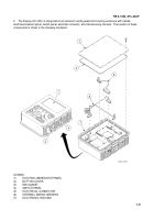
The Display Unit (DU) is the primary man–machine interface and displays system status, navigation
data, gun tube position, ammunition inventory, and test/diagnostic messages.
A menu driven display provides
prompts for data entry using a numeric keypad.
(3)
The Prognostic/Diagnostic Interface Unit (PDIU) performs prognostic and diagnostic functions on the
weapon system.
The PDIU tests, detects faults, and fault isolates Line Replaceable Units (LRUs) in the Electrical
System, Automatic Fire Control System (AFCS), Vehicle Hydraulic System, and Gun Position System.
(4)
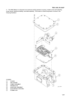
The Vehicle Motion Sensor (VMS) Modem provides a means to transmit digital vehicle motion data from
the motion sensor location in the hull, through the vehicle slip rings, to the ACU location in the cab.
(5)
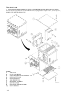
The Power Conditioning Unit (PCU) protects all electronic digital subsystems from power transients,
compensates for voltage drops and spikes, and continuously monitors system circuits for vehicle and battery
status.
b.
The Prognostic/Diagnostic Interface Unit (PDIU) performs prognostic and diagnostic functions on a weapon
system.
The PDIU tests, detects faults, and fault isolates Line Replaceable Units (LRUs) in the Electrical
System, Automatic Fire Control System (AFCS), Vehicle Hydraulic System, and Gun Position System.
Back to Top

