TM-9-1200-215-34-P - Page 20 of 266
TM 9–1200–215–34&P
1–8
1–16.
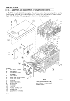
LOCATION AND DESCRIPTION OF MAJOR COMPONENTS
a.
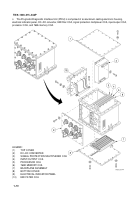
The AFCS Computer Unit (ACU) is comprised of an aluminum casting electronic housing with two handles,
connector panel, hard drive, 1553 CCA, Discrete I/O CCA, Servo CCA, TCIM CCA, CPU CCA, and a Power
Supply CCA.
The location of these components is shown in the following illustration:
LEGEND:
(1)
TOP PANEL COVER
(2)
EMI GASKET
(3)
CONNECTOR PANEL
ASSEMBLY
(4)
EMI GASKET
(5)
HARD DISK DRIVE COVER
(6)
HARD DISK DRIVE
(7)
1553 CCA
(8)
DISCRETE I/O CCA
(9)
SERVO CCA
(10)
TCIM CCA
(11)
CPU CCA
(12)
POWER SUPPLY CCA
(13)
BACKPLANE
(14)
ELECTRONIC HOUSING
7
1
2
3
4
6
5
8
9
10
11
12
13
14
NOTE
Cables and fasteners to CCAs
are not shown to improve clarity
of the illustration.
Back to Top

