TM-9-1240-401-34-P - Page 12 of 590
TM 9-1240-401-34&P
1-4. REPORTING EQUIPMENT IMPROVEMENT RECOMMENDATIONS (EIR’S)
If your equipment needs improvement, let us know, send us an EIR.
ElRs will be prepared using SF Form 368 (Quality
Deficiency Report). ElRs should be mailed directly to Director, U.S. Army Armament and Chemical Acquisition and Logistics
Activity, Attn.: AMSTA-AR-QAW-A (R)/Customer Feedback Center, Rock Island, Illinois 61299-7300.
1-4.1. CORROSION PREVENTION AND CONTROL (CPC)
Corrosion Prevention and Control (CPC) of Army materiel is a continuing concern.
It is important that any corrosion problem
with this item be reported so that the problem can be corrected and improvements can be made to prevent the problem in
future items.
While corrosion is typically associated with rusting of metals, it can also include deterioration of other materials such as rubbe
and plastic. Unusual cracking, softening, swelling, or breaking of these materials may be a corrosion problem.
If a corrosion problem is identified, it can be reported using Standard Form 368, Quality Deficiency Report. Use of key words
such as “corrosion”, “rust”, “deterioration”, or “cracking” will assure that the information is identified as a CPC problem.
The form should be submitted to: Commander, U.S. Army Armament Research, Development and Engineering Center, ATTN:
AMSTA-AR-QAW-A (R) /Customer Feedback Center, Rock Island, IL 61299-7300.
Section II. Equipment Description and Data
1-5. EQUIPMENT CHARACTERISTICS, CAPABILITIES, AND FEATURES
a.
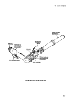
M146 Telescope Mount.
(1)
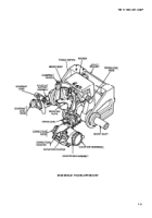
The M146 telescope mount provides an adjustable support for the M118A2/M118A3 elbow telescope. The M146
telescope mount consists of a yoke, a bracket, an elevation bracket, a base plate, an elevation knob mechanism, a deflection
knob mechanism, and a cable assembly.
(2)
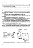
The yoke and the base plate are bolted to the howitzer cradle. The yoke has a pair of machined crosskeys that fit
into corresponding slots in pads machined onto the cradle to prevent shifting of the yoke during recoil. The yoke is secured to
the bracket by two yoke pins which fit into the opposite ends of a vertical bore in the bracket. The bracket is secured to the
main bracket of the M146 telescope mount.
(3)
The M118A2/M118A3 elbow telescope is supported in elevation by an elevation slide which travels on an arc
about the center of the telescope ball which fits into the forward end of the bracket. A keyed ratchet on the elevation slide
engages a slot on the main bracket to brace the M118A2/M118A3 elbow telescope against recoil. Lateral movement of the
elevation knob mechanism is prevented by a retainer plate which acts as a “T” slot key. The M118A2/M118A3 elbow telescope
is held in position by a tapered (king) pin which fits into matching holes on the telescope housing.
(4)
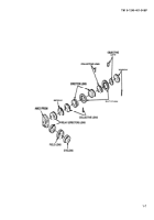
The M146 telescope mount adjusts the M118A2/M11BA3 elbow telescope for boresighting and ballistic corrections
by means of an elevation knob machined with an internal acme screw thread. Turning the elevation knob raises the elevation
slide, pivoting the M118A2/M118A3 elbow telescope vertically about the telescope ball. Elongated holes in the elevation
bracket permit an adjustment of +10 mils in elevation. Each revolution of the elevation knob represents an 8-mil angular
change in elevation, Elevation corrections are measured on a dial of angular deviations scored in tenths of a mil and numbered
1, 2, 3, 4, 5, 6, and 7 mils. A spring-loaded elevation ratchet automatically locks the controls at all even line increments on th
elevation dial.
1-2
Change 1
Back to Top

