TM-9-1240-401-34-P - Page 18 of 590
TM 9-1240-401-34&P
1-5. EQUIPMENT CHARACTERISTICS, CAPABILITIES, AND FEATURES - continued
c.
M145/M145A1 Telescope Mount.
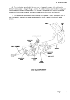
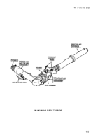
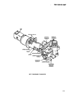
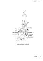
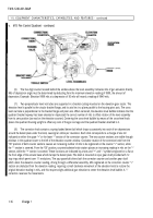
(1) The M145/M145A1 telescope mount supports and provides an adjustable base for the M117/M117A2 panoramic
telescope. It incorporates components which permit accurate adjustment of the weapon in elevation ±10°, and allows one-
man weapon operation. The M145/M145A1 telescope mount is rigidly installed in the cab of the vehicle, at the left front side
of the weapon breech.
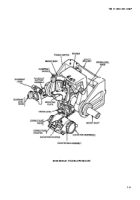
(2) The M145/M145A1 telescope mount is essentially a Hook’s universal joint, which allows adjustment of the verti-
cal axis of the M117/M117A2 panoramic telescope to remain plumb regardless of the pitch or cant of the vehicle. The
elevation measurements provided by the M145/M145A1 telescope mount and the azimuth measurements provided by the
M117/M117A2 panoramic telescope are true weapon elevation and azimuth. The major components of the M145/M145A1
telescope mount are a gun bar pivot which is the basic reference from which elevation and azimuth measurements and
adjustment are made; a mount body; a pitch knob, cross-level knob, and elevation handwheel with their associated
mechanisms; a rocker; a counter assembly; a mount bracket; and a quadrant support assembly, which is provided for
making fine elevation adjustments with a gunner’s quadrant. The upper rear portion of the mount body provides the seat for
the M117/M117A2 panoramic telescope. A pair of arms which extend upward from the body secures the M117/M117A2
panoramic telescope inaccurate vertical alinement with the body by means of clamping catches. Two tapered keyways on
the upper surface of a steel plate provide a wear-resistant mounting surface for the M117/M117A2 panoramic telescope
and mate with corresponding tapered keyways on the bottom of the M117/M117A2 panoramic telescope housing.
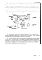
(3) The mount bracket is bolted to a vertical mounting bracket welded to the trunnion support in the left side of the
vehicle cab, forward of the trunnion. An alining plate, which contains keyways for the mount bracket keys, is installed be-
tween the mount bracket and the cab bracket so that the planes which contain the vertical surfaces of the keyways are
parallel to the trunnion axis. An arm extends forward from each side of the mount bracket to support the main shaft of the
M145/M145A1 telescope mount.
(4) Rotation of the pitch knob orients the vertical axis of the mount body for pitch adjustment within range of + 1O
O
. The
pitch knob, which Operates through a wormshaft and a gear segment, permits the mount body to be adjusted at all times to
a position corresponding to zero elevation.
(5) The cross-level knob rotates the mount body for deflection compensation as the weapon is being elevated or
depressed. Rotation of the cross-level knob orients the mount body to the true vertical firing plane of the gun. Cross-level
adjustment is limited to ±10°.
(6) Rotation of the elevation handwheel elevates or depresses the M145/M145A1 telescope mount.
(7) The pitch level, cross-level, and elevation level are installed in housings integral with the lower portion of the
mount body. When the bubbles in the pitch level and cross-level are centered, the vertical axis of the M117/M117A2 pano-
ramic telescope is plumb and in a plane with the true firing plane of the gun. The elevation level gives an indication of true
weapon elevation regardless of trunnion cant. Each level vial is protected by a cover and can be adjusted by an eccentric.
LEDs, installed at the ends of the level vials, illuminate the bubbles. Mirrors, set at 45° angles, permit viewing of the bub-
bles.
(8) The elevation counter, located on the lower portion of the mount body, measures and calibrates, in mils, the
elevation of the M145/M145A1 telescope mount. The elevation counter is capable of reading from 0000 to 9999 mils. How-
ever, a series of stop rings arranged on the elevation handwheel shaft limits rotation of the elevation handwheel so that the
effective range of the elevation counter is from 9950 (corresponding to an elevation of -50 mils) upward through 0000 to
1383 mils.
1-8
Back to Top

