TM-9-1240-401-34-P - Page 24 of 590
TM 9-1240-401-34&P
1-5. EQUIPMENT CHARACTERISTICS, CAPABILITIES, AND FEATURES - continued
d.
M117/M117A2 Panoramic Telescope - continued.
(18)
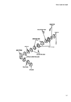
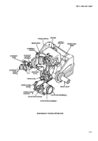
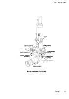
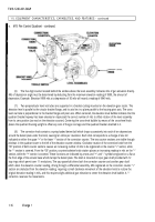
The gunner’s aid counters in the gunner’s aid housing assembly are connected to the reset counter and to the
gunner’s aid knob. Rotating the gunner’s aid knob drives both the gunner’s aid counters and the reset counter simultaneously.
Provided the gunner’s aid counters are initially set at zero and the reading on the reset counter is observed, the M117/M117A2
panoramic telescope operator can set in a given deviation with the gunnel’s aid knob. The magnitude of the deviation appears
in the dials of the gunner’s aid counters and changes the reading in the reset counter. Left deviations, which move the strike
point to the left, are read in the upper gunner’s aid counter window; tight deviations, which move the strike point to the right,
are read in the lower window. A series of stop rings limit the gunner’s aid knob to 10 turns, or + 50 mils of correction.
(19)
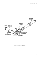
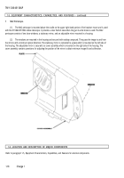
A tapered keyway under the front side of the lower M117/M117A2 panoramic telescope housing rests upon mating
tapered keys on the M145/M145A1 telescope mount. A key on each side of the upper telescope housing fits into keyways in
the M145/M145A1 telescope mount to support the M117/M117A2 panoramic telescope. A clevis on each side of the upper
telescope housing is engaged by a clamping catch on the M145/M145A1 telescope mount to hold the M117/M117A2
panoramic telescope in place.
(20)
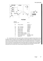
Placing the M117/M117A2 panoramic telescope on the M145/M145A1 telescope mount automatically connects the
electrical power needed to operate the reticle, and counter LEDs. An insulated positive contact assembly mates with a
corresponding contact built into the M145/M145A1 telescope mount, Single-conductor wires connect to the variable resistors
and to the LEDs. The LEDs are grounded to the telescope body and the circuit is completed through the metal-to-metal mating
surfaces between the M117/M117A2 panoramic telescope and the M145/M145A1 telescope mount. Rotation of the variable
resistor knobs on the lower portion of the upper telescope housing dims or brightens the reticle LEDs and the LEDs in the
overlay assembly which illuminate the counters.
e.
M15 Fire Control Quadrant.
1-14
Change 1
Back to Top

