TM-9-1240-401-34-P - Page 26 of 590
TM 9-1240-401-34&P
1-5. EQUIPMENT CHARACTERISTICS, CAPABILITIES, AND FEATURES - continued
e. M15 Fire Control Quadrant - continued.
(6)
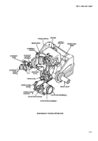
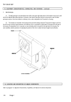
The four-digit counter located behind the window above the level assembly indicates mils of gun elevation directly.
Mils of depression angle must be determined by deducting from the maximum elevation reading of 9999, the amount of
depression. Example: Elevation 9999 mils at a depression of 50 mils will record a reading of 9949 mils.
(7)
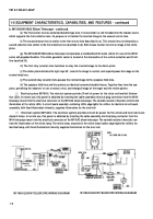
Two perpendicular level vial tubes are supported in a bracket casting mounted on the elevation gear sector. The
elevation level is parallel to the circular bracket flange, and its axis lies in a plane parallel to the housing pivot axis. The cross
level vial tube is perpendicular to the bracket flange and pivot axis. When centered, the elevation level bubble indicates that the
quadrant bracket keyway has been elevated or depressed the correct number of mils to offset rotation of the level assembly
from its zero position (as read on the elevation counter). Centering the cross-level bubble by means of the cross-level knob
places the quadrant housing upright to offset any cant of the gun carnage and the quadrant bracket attached to it.
(8)
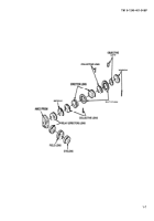
The correction knob contains a spring loaded detent ball which drops successively into each of ten depressions
around the detent plate under the knob, causing ten clicks per revolution. Each click corresponds to a change of one mil
indicated on either the upper “+” or the lower “-” section of the correction counter. The two counter sections are visible through
windows in the quadrant cover to the left of the elevation counter window. Clockwise rotation of the correction knob from the
"00" position of both counter sections causes an increasing number of mils to be registered on the counter “+” section, while
the "-" section is covered. From the "00" position, counterclockwise knob rotation places an increasing reading in mils on the "-"
section, while the "+" section is coveted. These functions are indicated by arrows and "+" and "-" symbols engraved on a flat at
the front edge of the annular base which clamps the detent plate. The knob is mounted on spur gear-shaft provided with 12
stop rings which permit over 11 revolutions. The spur gearshaft drives both the correction counter and another gear shaft
which alters the elevation counter reading, driving through a differential assembly. Mils registered on the correction counter "+"
section are deducted from the elevation reading, requiring a small clockwise movement of the elevation knob to restore the
original elevation reading in mils, and this requires slight additional gun elevation to center the elevation level bubble. A "-"
correction reverses the movements.
1-16
Change 1
Back to Top

