TM-9-1240-401-34-P - Page 16 of 590
TM 9-1240-401-34&P
1-5 EQUIPMENT CHARACTERISTICS, CAPABILITIES, AND FEATURES - continued
b. M118A2/M118A3 Elbow Telescope - continued.
(e) The first erector lens isa cemented doublet-type lens. It is mounted in a cell threaded into the tubular sleeve
which supports the first collective lens. Its purpose is to transfer the inverted image to the second erector lens.
(f) The second erector lens is similar to the first erector lens described in (e). This erector lens is followed by a
second collective lens similar to the first collective lens described in (d). Both lenses function to form an image at the reticle
plane.
(g) The M118A2/M118A3 elbow telescope incorporates a standardized mil scale reticle for use on the Ml 09
series self-propelled howitzer. The reticle geometric center is located at the intersection of the vertical centerline and 20 mil
line (marked 20).
(h) The first relay (erector) lens functions to relay the inverted image to the Amici prism.
(i) The Amici prism deviates the light rays 90°, reverts the image to normal, and superimposes the image on the
second relay lens.
(j) The second relay (erector) lens passes the normal image to the eyepiece field lens.
(k) The eyepiece field lens and the eyelens are identical cemented doublet lenses. Together they form the eye-
piece, permitting the observer to see a normal, erect, and enlarged image of the target and the reticle pattern.
(6)
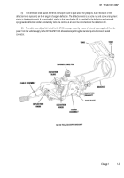
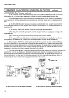
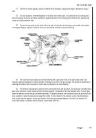
Electrical system (M118A3). The electrical system provides 24-volt dc power for the reticle and Ievelvial illumina-
tion LEDs. In normal use, this power is obtained by inserting the cable assembly electrical plug connector from the Ml 46
telescope mount into the electrical connector of the M118A3 elbow telescope. The variable resistor (rheostat) controls the
illumination of the reticle LEDs. A circuit board assembly containing LEDs edge-lights the retitles. An identical circuit board
assembly, with fixed illumination intensity, supplies illumination for the level vial
(7)
Electrical system (M118A2). The electrical system provides 24-volt dc power for the reticle and level vial incan-
descent lamps. In normal use, this power is obtained by inserting the cable assembly electrical plug connector from the
M146 telescope mount into the electrical connector of the M118A2 elbow telescope. The variable resistor (rheostat) con-
trols the illumination of the reticle lamp. The reticle lamp, mounted in the reticle lamp holder, edge-lights the retitles. An
identical lamp, with fixed illumination intensity supplies illumination for the level vial.
M118A3 ELBOW TELESCOPE WIRING DIAGRAM
1-6
M118A2 ELBOW TELESCOPE WIRING DIAGRAM
Back to Top

