TM-9-1240-401-34-P - Page 22 of 590
TM 9-1240-401-34&P
I
1-5. EQUIPMENT CHARACTERISTICS, CAPABILITIES, AND FEATURES - continued
I
d. M117/M117A2 Panoramic Telescope-continued.
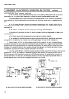
(7) The etched sutface of the reticle is located in the focal plane of the objective Ienses so that the graduations and the
target image can be superimposed. The edge of the reticle is illuminated by LEDs connected to the holders. The reticle
pattern consists of a horizontal and a vertical centerline. The horizontal centerline is graduated into 5 mil increments by
short vertical lines. Alternate graduations on each side of the vertical centerline are numbered consecutively every 10 mils,
from 10 to 80.
(8) The reticle illuminating lens is a plastic piano-convex lens which transmits light from a LED installed in the tele-
scope body to edge-light the reticle.
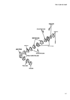
(9) The erecting lenses are cemented doublet lenses. With the dove prism and the Amici prism, the two erecting
lenses assist in presenting a normal image of the target and the reticle pattern in the focal plane of the eyepiece. Primarily,
the erecting lenses serve to lengthen the light path through the telescope tube without requiring an increase in the tube
diameter. The lenses provide parallel rays of light through the dove prism.
(10) The dove (or rotating) prism is a refracting type prism. The parallel rays of light from the erecting Ienses strike the
upper 45-egree face of the dove prism and are refracted toward the center of the longest surface of the prism, which in
turn reflects the light rays toward the lower 45-degree surface of the dove prism. The rays are refracted once again as they
pass from the dove prism. The dove prism is rotated at one-half the speed of the 90-degree prism of the Amici prism, and
with these prisms assures that the target image, as seen by the observer, does not rotate about the line of sight as the head
and/or the eyepiece are rotated in azimuth.
(11) The Amici prism bends the light rays 90° and inverts and reverts the image so that an erect and normal image of
both target and reticle pattern are formed in the focal lens of the eyepiece.
(12) The diaphragm located in the eyepiece focal plane, functions as a stop to exclude undesirable light from the
image.
(13) The field lens and the eyelens are similar cemented doublet lenses. Together they form the eyepiece, which
permits the observer to see a normal, erect, and enlarged image of the target and reticle pattern.
(14) Rotation of the azimuth knob causes the 90-degree prism to rotate in cross-level. The azimuth knob also causes
rotation of the dove prism assembly at half the speed of the 90-degree prism.
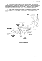
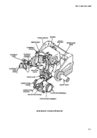
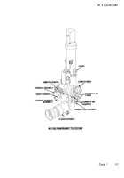
(15) The counters are part of a counter adapter assembly which fits into the Iower telescope housing. Rotation of the
azimuth knob causes the azimuth counter to register azimuth travel in mils. The azimuth counter assembly is a 3-dial,
4-digit instrument with a numerical range from 0000 to 6399. A series of graduation marks divides the area into quarter-roil
increments for greater accuracy insetting. The external end of the countershaft is slotted so that it may be pushed in and
turned with a screw driverto set the counter to a reading of 3200 roils for boresighting. A spring-loaded door covers the dial
of the azimuth counter on the face of the counter adapter assembly. A rod, when pushed, disengages the detent which
holds this door shut, causing the door to snap open. An overlay assembly containing LEDs, mounted on the counter
adapter between the azimuth counter and the reset counter, illuminates the two counter dials.
(16) The azimuth counter is connected to a 3200-mil reset counter. The reset counter is a standard 4-digit, high-
speed counter with a numerical range from 0000 to 9999. The right-hand dial is graduated in quarter-roil increments for
greater accuracy insetting. An index line is marked on the cover of the reset counter. Normally, the reset counter is driven
to register the telescope azimuth travel, in mils, when the azimuth knob is rotated. The reset counter maybe reset at any
time to 3200 roils by pushing in and turning the reset knob.
(17) Rotation of the elevation knob causes the 90-degree prism to be elevated or lowered through a travel of ±300
roils. Clockwise rotation of the elevation knob causes the 90-degree prism to tilt upward and counterclockwise rotation
causes the 90-degree prism to tilt downward.
1-12
Back to Top

