TM-9-1240-401-34-P - Page 14 of 590
TM 9-1240-401-34&P
1-5. EQUIPMENT CHARACTERISTICS, CAPABILITIES, AND FEATURES - continued
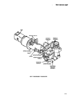
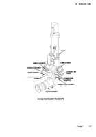
b. M118A2/M118A3 Elbow Telescope.
(1)
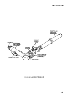
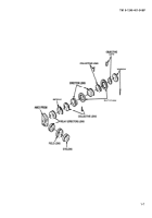
The M118A2/M118A3 elbow telescope is the basic direct fire instrument used for positioning the weapon in
azimuth and elevation on targets visible from the weapon. The M118A2/M118A3 elbow telescope is mounted, by means of
spherical seats and retaining kingpin, on the M146 telescope mount. The M118A2/M118A3 elbow telescope is a 4-power,
fixed-focus telescope with a 10° field of view. It consists of three major subassemblies: the eyepiece and erector lens sub
assembly (also referred to as the eyepiece arm), the reticle cage and cant corrector subassembly, and the objective and
diaphragm subassembly. These are the basis of telescope control and adjustment.
(2)
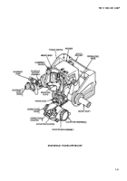
Eyepiece and erector lens subassembly (eyepiece arm).
(a)
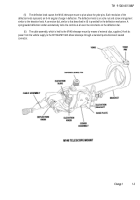
This subassembly pivots about the line of sight of the M118A2/M118A3 elbow telescope. It is operated by
means of an external lock-release lever and can be locked in position at any desired angle. Although the travel of the eyepiece
arm is normally limited to +20 from the horizontal, it is possible to depress the limiting stops to allow 180° rotation of the
eyepiece arm. The eyepiece is fitted with a rubber eyeshield which serves to eliminate unnecessary light and to maintain
proper eye distance while sighting through the M118A2/M118A3 elbow telescope.
(b)
This subassembly also contains the eyelens and field lens, the relay (erector) lenses and the Amici prism.
(c)
Enclosed in separate housing on the eyepiece arm is a variable resistor (rheostat) which controls illumination
of the reticle.
(d)
A valve on the eyepiece arm provides for pressurization of the M118A2/M118A3 elbow telescope.
(3)
The reticle cage and cant corrector subassembly. This section provides movement of the M118A2/M118A3 elbow
telescope and contains the precollimated ballistic reticle. A pair of wormshaft assembly (cant correction) knobs are used in
conjunction with the level assembly. The level vial is used by the gunner to cross-level the cant corrector whenever it is in a
canted position. For easy viewing, the level vial is provided with a mirror.
(4)
Objective and diaphragm subassembly. This subassembly contains the objective lens, diaphragms, collective lens,
and erector lenses.
(5)
Optical system. All optical components of the M118A2/M118A3 elbow telescope are internally mounted in the three
main subassemblies as previously described. The optical system is composed of a window, an objective lens, a diaphragm, a
collective lens, a first erector lens, a diaphragm, a second erector lens, a collective lens, three reticles (either of which can be
moved into a common focal plane), a first relay (erector) lens, an Amici prism, a second relay (erector) lens, a field lens, and
an eyelens. All optical elements are fixed in position and hermetically sealed in the M118A2/M118A3 elbow telescope.
(a)
The window is mounted in a threaded cell in the objective end of the forward tube. It protects the optical
system from dirt, dust, and moisture.
(b)
The objective lens is a cemented doublet-type which is mounted directly behind the window in an
independently sealed cell. It forms an inverted and reverted image of the target at the diaphragm.
(c)
The diaphragm, which functions as a field of view stop, limits the field of view to the desired value and at the
same time provides a well-defined cutoff to the field of view. It is located in the focal plane of the objective lens.
(d)
The first collective lens is a piano-convex lens retained in a tubular sleeve by the threaded cell that supports
the diaphragm. The function of the collective lens is to form a well-defined image of the target to the first erector lens.
1-4
Back to Top

