TM-9-1240-401-34-P - Page 213 of 590
TM 9-1240-401-34&P
5-23. ADAPTER ASSEMBLY MAINTENANCE INSTRUCTIONS
his task covers:
a.
Removal/Disassembly b.
Repair
c.
Assembly/Installation
INITIAL SET-UP
Tools
Soldering iron (item 24, appx F)
Tool Kit, Electronic System, Repair, Field Mainte-
nance (SC5180-95-CL-B29)
Tubular spanner wrench, 11/16 and 45/64 inch
(Item 26, appx F)
Materials/Parts
Lockwashers (2) (Item 65, appx E)
Sealing compound (Item 13, appx B)
Solder (Item 18, appx B)
References
TM 9-254
Equipment Condition
Adhesive (Item 2, appx B)
Flux (Item 5, appx B)
Lockwasher (Item 63, appx E)
Lo&washers (5) (Item 64, appx E)
M117/M117A2 panoramic telescope removed from
howitzer (TM 9-2350-311-101
TM 9-2350-314-10)
Counter assembly removed from M117/M117A2
panoramic telescope (ref. para 5-22)
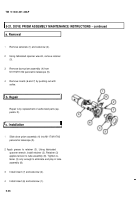
a. Removal/Disassembly
1
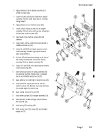
Remove machine screw (1), lockwasher (2),
retaining strap (3), and light conductor (4). Discard
lockwasher.
2
Remove headless straight pin (5) securing gear in
mechanical housing (6) to gear shaft (7).
3
Remove machine screw (8) and two machine
screws (9) from adapter assembly (10).
4
Carefully slide mechanical housing (6) from gear
shaft (7).
Change 1
5-39
Back to Top


