TM-9-1240-401-34-P - Page 222 of 590
TM 9-1240-401-34&P
5-26. M117/M117A2 PANORAMIC TELESCOPE FINAL INSPECTION AND ADJUSTMENT
- continued
INITIAL SET-UP
Collimator, telescope 5800955
Dioptometer holder (Item 19, appx F)
Fixture, testing, azimuth (Item 17, appx F)
Precision level (Item 20, appx F)
Projector, collimating (Item 21, appx F)
Tools
Purging kit (Item 22, appx F)
Tool Kit, Electronic System, Repair, Field Mainte-
nance (SC5180-95-CL-B29)
Torque adapter (Item 1, appx F)
Torque adapter (Item 2, appx F)
Torque adapter (Item 6, appx F)
Torque adapter (Item 7, appx F)
Torque wrench (in-lb) (Item 36, appx F)
Materials/Parts
Grease (Item 7, appx B)
Nitrogen, technical (Item 8, appx B)
Sealing compound (Item 13, appx B)
Shim stock (Item 19, appx B)
Tape (Item 20, appx B)
I
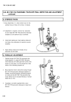
a. SETTING UP AZIMUTH TESTING FIXTURE
1
2
3
4
5
Install azimuth testing fixture (1) on test stand (2)
at a height suitable for operation.
Position precision level (3) on azimuth testing fix-
ture (1).
Adjust three leveling screws (4) until level (5) bub-
ble remains centered through one full rotation of
azimuth testing fixture (1).
Remove precision level (3).
Set azimuth fixture ring (6) so “0” graduation marks
coincide and lock azimuth fixture ring (6).
5-48
Back to Top


