TM-9-1240-401-34-P - Page 227 of 590
TM 9-1240-401-34&P
5-53
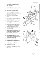
f. IMAGE TILT ADJUSTMENT
1
2
3
4
5
6
7
8
9
Position pre-plumbed collimating projector (1) at
level of window in cap (2) of M117/M117A2 pano-
ramic telescope so that the two optical axes lie in
parallel planes.
Check image tilt through one full revolution of the
cap (2) in each direction. The image of the vertical
reticle line shall be vertical within 2° (0.62 mils) of
arc. This requirement shall also be met with the
elbow assembly positioned against each of the
swing stops at each azimuth setting.
If image tilt is not within specified limits, remove
three machine screws (3) and access cover (4).
Remove setscrew (5) from shaft (6).
Insert hexagon key into center of shaft (6) and turn
until image of the vertical reticle line is within 2°
(0.62 mils) of arc. (Ref. TM 9-254 for conversion to
roils.)
Remove hexagon key and replace setscrew (5). Be
careful not to disturb established position.
Recheck image tilt as directed in steps 1 and 2.
If necessary, repeat steps 4,5, and 6.
Install access cover (4) and secure with three
machine screws (3).
Back to Top


